Projector
A projector, projection lens technology, used in television, optics, instruments, etc.
- Summary
- Abstract
- Description
- Claims
- Application Information
AI Technical Summary
Problems solved by technology
Method used
Image
Examples
Embodiment 1
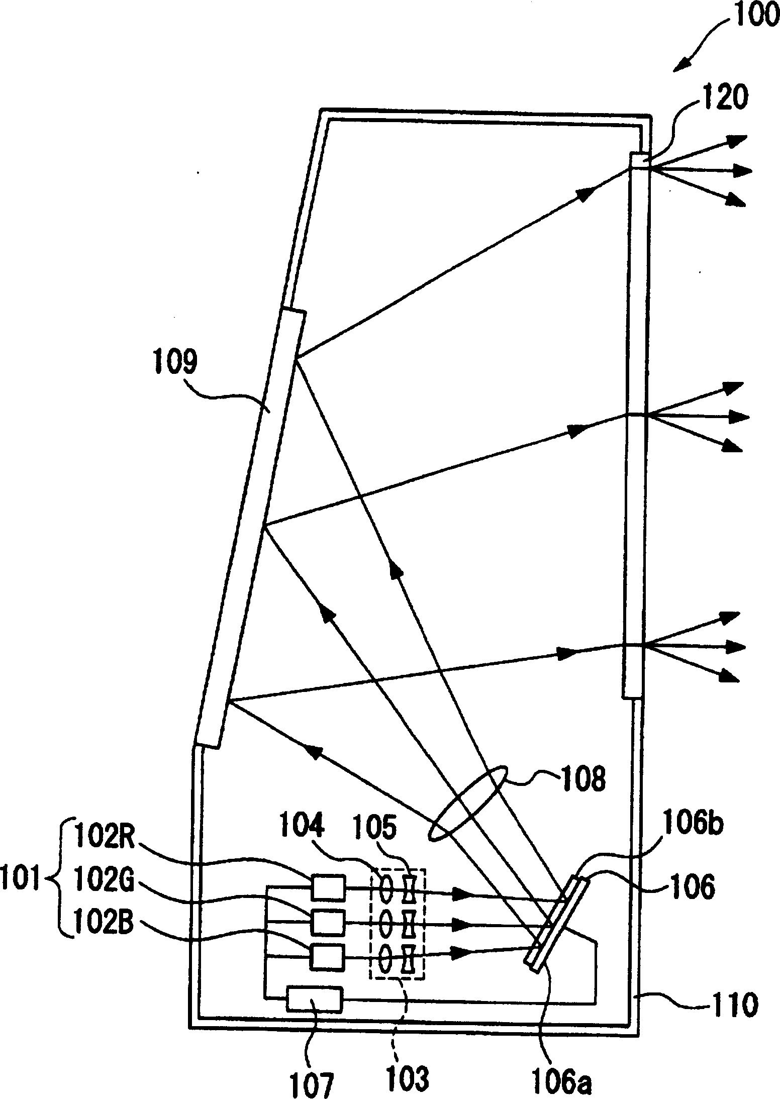
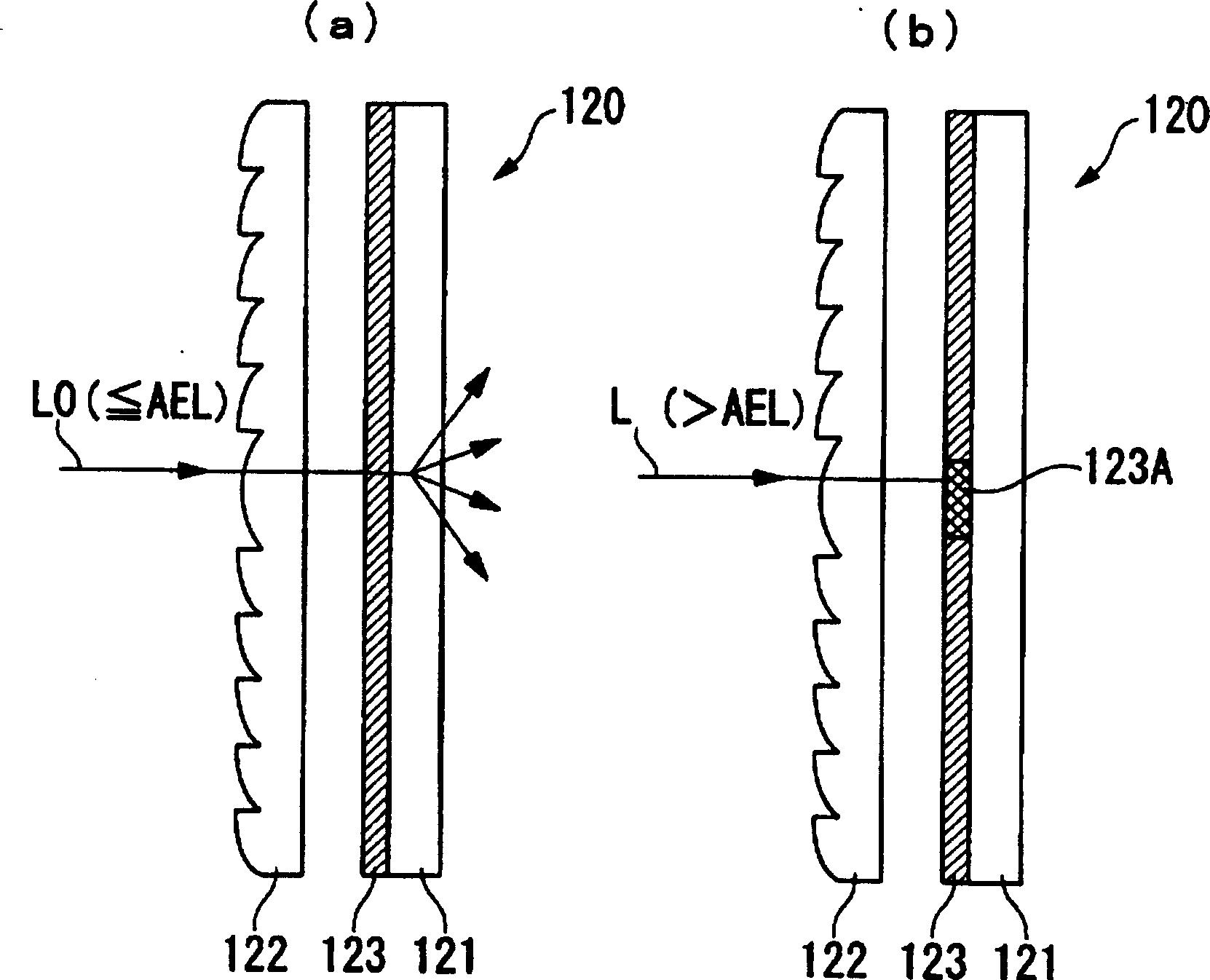
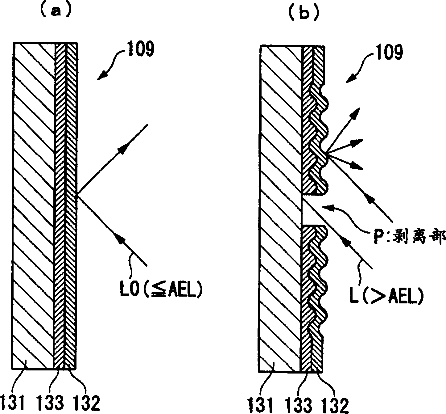
[0035] figure 1 It is a schematic diagram showing the configuration of the projector according to Embodiment 1 of the present invention. The projector 100 of this embodiment is mainly composed of a light source 101 that emits laser light, a lens optical system 103 including a collimating optical system 104 and a beam shaping optical system 105, a scanner 106 that scans the incident laser light in a two-dimensional direction, and A projection lens 108 for enlarging and projecting the scanned light and a mirror 109 for reflecting the projected light toward a screen 120 are configured. In this projector 100, a light source 101, a lens optical system 103, a scanner 106, a projection lens 108, and a mirror 109 are housed inside a housing 110 having a screen 120, and laser light propagating in the housing 110 is 120 to scan and display images.
[0036] Next, the structure and function of the projector of this embodiment will be described.
[0037]The light source 101 is composed ...
Embodiment 2
[0068] Image 6 It is a schematic diagram showing the configuration of a projector according to Embodiment 2 of the present invention.
[0069] Such as Image 6 As shown in (a), the projector 200 of this embodiment is mainly composed of a light source 101 that emits laser light, a lens optical system 103 including a collimating optical system and a beam shaping optical system, and a scanning system that scans the incident laser light in a two-dimensional direction. A device 106 , a condensing optical system 150 for condensing the scanned light, a mirror 160 for reflecting the condensed light, and an enlarging optical system 108 for enlarging and projecting the reflected light onto the screen 120 .
[0070] In this projector 200 , laser light emitted from a light source 101 is shaped into approximately parallel light with high directivity by a lens optical system 103 , and then scanned in two-dimensional directions by a scanner 106 . The light emitted from the scanner 106 is ...
Embodiment 3
[0075] Figure 7 It is a schematic diagram showing the configuration of a projector according to Embodiment 3 of the present invention.
[0076] Such as Figure 7 As shown, the projector 300 of this embodiment is mainly composed of a light source 101 that emits laser light, a lens optical system 103 including a collimating optical system and a beam shaping optical system, and a scanner 106 that scans the incident laser light in a two-dimensional direction. , a mirror 160 that reflects the scanned light, and an enlarging optical system 170 that enlarges and projects the reflected light onto the screen 120 .
[0077] In this projector 300 , laser light emitted from a light source 101 is shaped into approximately parallel light with high directivity by a lens optical system 103 , and then scanned in two-dimensional directions by a scanner 106 . The light emitted from the scanner 106 is reflected by the mirror 160 toward the curved mirror 170 serving as a magnifying optical syst...
PUM
| Property | Measurement | Unit |
|---|---|---|
| Wavelength | aaaaa | aaaaa |
Abstract
Description
Claims
Application Information
 - R&D Engineer
- R&D Manager
- IP Professional
- Industry Leading Data Capabilities
- Powerful AI technology
- Patent DNA Extraction
Browse by: Latest US Patents, China's latest patents, Technical Efficacy Thesaurus, Application Domain, Technology Topic, Popular Technical Reports.
© 2024 PatSnap. All rights reserved.Legal|Privacy policy|Modern Slavery Act Transparency Statement|Sitemap|About US| Contact US: help@patsnap.com


