
Vacuum regulating valve

A pressure regulating valve and vacuum technology, applied in the direction of safety valves, balance valves, valve devices, etc., can solve the problem of driving the retaining ring by a small motor, and achieve the effects of miniaturization, power saving, and excellent economy

Active Publication Date: 2006-02-15
SMC CORP
View PDF2 Cites 31 Cited by
  • Summary
  • Abstract
  • Description
  • Claims
  • Application Information

AI Technical Summary

Problems solved by technology

However, if only the position adjustment of the stop ring is performed, a small and low-cost motor can be used, but since the above-mentioned piston presses the position adjustment stop ring with a large driving force, it is necessary to support the stop ring so as to be able to withstand Due to this driving force, and under the action of this driving force, it is difficult to use a small motor to drive the retaining ring, so this countermeasure needs to be considered

Method used


Image

  • Vacuum regulating valve

Examples


Embodiment Construction

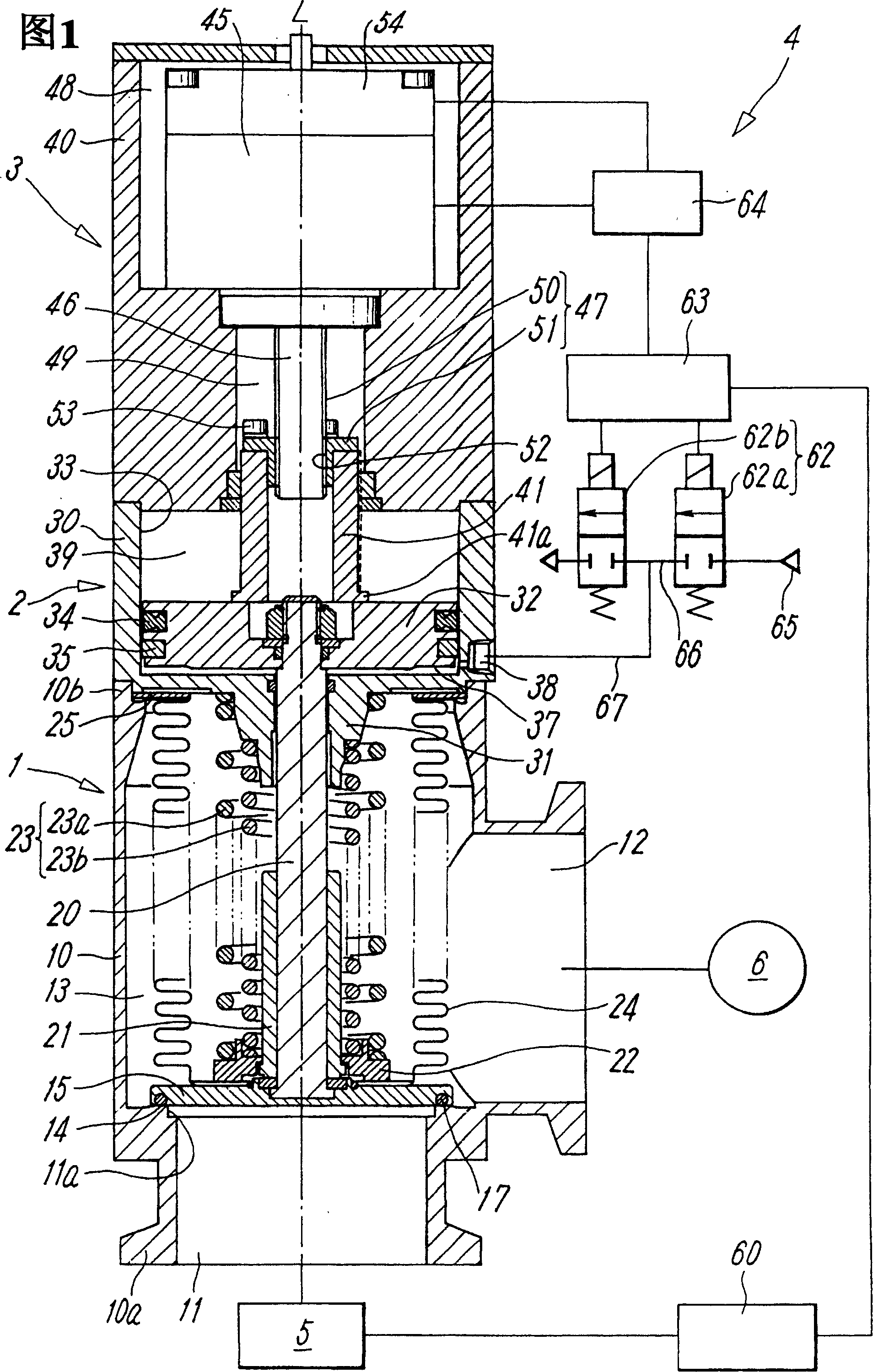
[0024] Fig. 1 shows a preferred representative embodiment of the vacuum pressure control valve of the present invention. This valve consists of a valve main body 1 having a valve member 15 for opening and closing the flow path 13 between the main gas ports 11 and 12; The cylinder part 2 of the valve member 15; the valve opening adjustment part 3 for setting the opening degree of the above-mentioned valve member 15; The valve main body 1, the cylinder 2 and the valve opening adjustment part 3 are connected in series along the axis L of the valve.

[0025] The above-mentioned valve body part 1 essentially has a cylindrical or prism-shaped hollow valve casing 10, on which a first main gas port 11 for connecting with the vacuum chamber 5 is arranged, and for connecting with the vacuum chamber 5. The second main air port 12 connected to the vacuum pump 6, the above-mentioned first main air 11, is on the side of the first end 10a of the valve housing 10, and opens in the direction o...


PUM


Abstract

To provide a well controllable vacuum pressure regulating valve with a valve member whose opening is quickly and accurately controlled by a small and inexpensive electric motor. The vacuum valve regulating valve comprises a valve main part 1 using a valve member 15 for opening / closing a valve seat 14 between main ports 11, 12, a cylinder part 2 having a piston 32 for opening / closing operation of the valve member, a valve opening adjusting part 3 using a stopper 41 to be driven by the electric motor 45 for setting the opening of the valve member, and a valve control part 4 for controlling the opening of the valve member in accordance with the output of a pressure sensor 60 in a vacuum chamber. The valve control part has a main controller 63 for outputting a signal which determines the opening of the valve member, to a motor controller 64 which controls the electric motor 45, in accordance with a signal for a pressure set value and a pressure signal from the pressure sensor and for controlling the supply of pilot fluid to a pressure chamber 37 of the piston to move the piston 32 to a position where it abuts on the stopper.

Description

technical field [0001] The present invention relates to a vacuum regulator used for decompression and the like in a vacuum chamber for a chemical reaction in a physical chemical machine or the like. Background technique [0002] For example, in semiconductor manufacturing equipment, chemical processing such as etching is performed in a vacuum chamber. At this time, a vacuum pump is used to depressurize the vacuum chamber, and a vacuum valve is used to open and close the external flow path connecting the vacuum pump and the vacuum chamber. This vacuum valve, as described in Patent Document 1, has two gas ports connected to a vacuum pump and a vacuum chamber; an internal flow path connecting these gas ports; a valve seat formed in this internal flow path; and opening and closing the valve seat and open and close the piston of the valve part, so that the stroke of the piston directly becomes the valve opening when the above-mentioned valve part opens the valve seat. [0003] H...

Claims


Application Information

Patent Timeline
Patent Type & Authority Applications(China)
IPC IPC(8): F16K17/06G05D16/00F16K51/02
CPCG05D16/202Y10T137/7761Y10T137/8242E01D15/133E01D19/005E01D2101/30
Inventor 梶谷昌生平松和夫
Owner SMC CORP
Learn More