High speed safety shockproof turnout for railway

A high-speed and railway technology, applied in the direction of roads, tracks, buildings, etc., can solve the problems of restricting the running speed of high-speed trains, reducing operating efficiency, increasing train energy consumption, etc., and achieving the effect of shortening running time, significant economic benefits, and light weight.

Inactive Publication Date: 2006-02-08
HEFEI BOPU HIGH TECH
View PDF0 Cites 4 Cited by
  • Summary
  • Abstract
  • Description
  • Claims
  • Application Information

AI Technical Summary

Problems solved by technology

[0002] At present, countries in the world generally use moveable turnouts on high-speed railways. The switch is realized by moving the switch rail between the straight track and the turnout. The maximum allowable speed of the train is about 110 kilometers per hour, and the maximum allowable speed of the train when passing the turnout is about 95 kilometers per hour, so that the high-speed train has to slow down when passing the turnout, which seriously restricts the running speed of the high-speed train on the line. Reduce operational efficiency while also increasing train energy consumption

Method used


Image

  • High speed safety shockproof turnout for railway
  • High speed safety shockproof turnout for railway
  • High speed safety shockproof turnout for railway

Examples


Embodiment 1

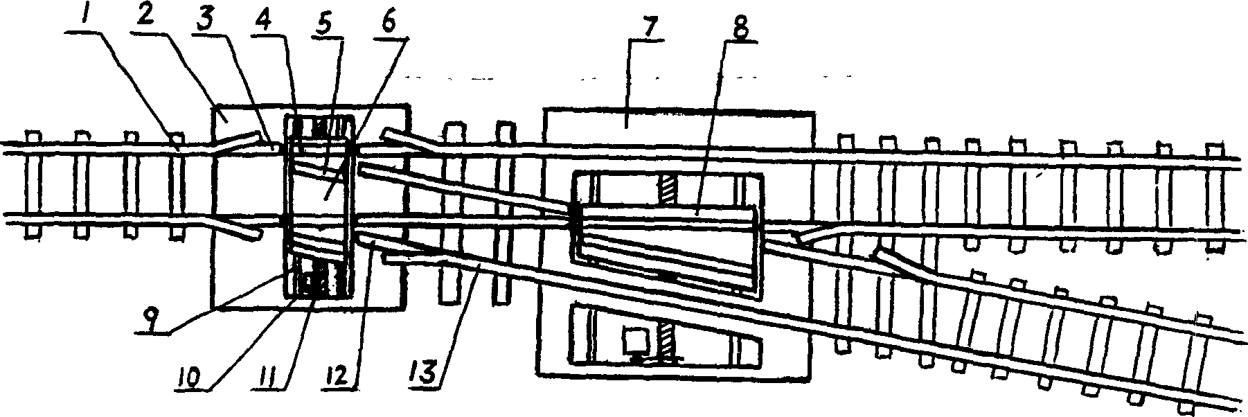
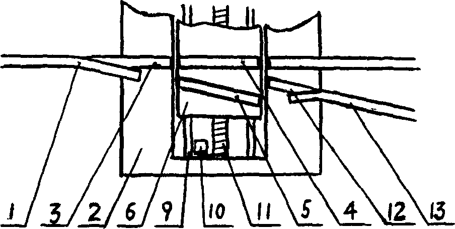
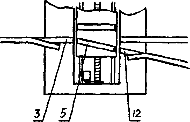
[0013] see figure 1 , as shown in the figure, a turnout sleeper 2 is set under the turnout part in the railway track line, and a turnout sleeper 7 is set under the place where the turnout track on one side crosses the straight track on the other side, and the turnout sleeper 2 and the turnout sleeper 7 A ram 6 and a ram 8 are respectively provided in the chute, and two straight transition rails 4 and two branch transition rails 5 are provided on the ram 6; a straight transition rail and a On the turnout transition rail, the rams 6 and 8 are respectively installed in the chute of the turnout sleeper through the guide rod 9 and the screw rod 11. One end of the screw rod 11 is connected with the motor 10 through the gear set, and the motor 10 drives the screw rod through the gear set to drive the internal gear in the ram. Threads to allow the ram to move in the chute.

[0014] The rail joint fixedly installed on the top of the turnout sleeper adopts a seamless telescopic connect...

Embodiment 2

[0018] see image 3 and Figure 3-1 , in the three-track line with the top rail erected by the door frame 22, a switch is installed in the rail below the door frame 22 and in the top rail above the door frame at the same time, wherein the switch in the rail is the same as in Embodiment 1, and the top rail switch The working principle of the structure is also the same as that of the switch in embodiment 1, and the top track switch and the road track switch work synchronously to complete the conversion between the straight line and the branch line.

[0019] As shown in the figure, the top track switch is composed of a top rail sleeper 19 and a ram 23 located in the chute of the top rail sleeper. The ram 23 is also provided with a straight transition top rail 20 and a branch transition top rail 21. The straight transition top rail Or the branch transition top rail is located between the straight top rail joints 18 set on the top rail sleeper, or between the straight transition t...


PUM


Abstract

The high speed safe railroad switch consists of sleepers, sliding sleepers and transition rails, and features that the sliding sleepers are driven with some drier to move inside the sleeper grooves so as to drive the straight transition rails and the turnout transition rails to move separately in the straight line and the turnout line to realize switch conversion. The present invention has simple structure, stable and reliable operation, less vibration, swinging and noise, and makes it possible to raise the train passage speed limit from available 95-110 km / hr to 200-300 km / hr. The present invention is also suitable for subway, light railway and three rail high speed line.

Description

technical field [0001] The invention relates to a turnout device used on railway track lines, in particular to a safe and anti-shock railway turnout which can allow trains to pass through at high speed. Background technique [0002] At present, countries in the world generally use moveable turnouts on high-speed railways. The switch is realized by moving the switch rail between the straight track and the turnout. The maximum allowable speed of the train is about 110 kilometers per hour, and the maximum allowable speed of the train when passing the turnout is about 95 kilometers per hour, so that the high-speed train has to slow down when passing the turnout, which seriously restricts the running speed of the high-speed train on the line. Reduce operational efficiency, but also increase the energy consumption of trains. Contents of the invention [0003] The invention provides a ram in the sleeper under the turnout, and by moving t...

Claims


Application Information

Patent Timeline
IPC IPC(8): E01B7/14
Inventor 李孝龙
Owner HEFEI BOPU HIGH TECH
Why Eureka
Try Eureka