
Mirco-traumatic skull drill

A technology of cranial drill and drill body, applied in the field of minimally invasive cranial drill, can solve the problems of high cost, non-use, time-consuming operation, etc.

Inactive Publication Date: 2006-02-08
张庆林
View PDF2 Cites 13 Cited by
  • Summary
  • Abstract
  • Description
  • Claims
  • Application Information

AI Technical Summary

Problems solved by technology

Because the ratio of the rotational speed of the drill bit to the handle of the traditional hand-operated cranial drill is 1:1, the drilling speed is slow, the operation is time-consuming and laborious, and the patient's bleeding volume increases, so the patient suffers a lot, especially in emergency treatment. When craniotomy is urgently needed in the crisis of brain herniation, the rescue time is often delayed due to the complexity of the craniotomy, which affects the therapeutic effect
Although electric drills and pneumatic drills increase the drilling speed, their structures are complex and expensive, requiring AC power or high-pressure nitrogen as a power source, which is neither convenient nor safe to use, and must be completed in the operating room
In addition, the preoperative preparations using electric drills or pneumatic drills are more complicated and easy to cause pollution, so they are generally not used
The application number is 92112056.7 (publication number CN1084730A) fast hand-operated craniotomy drill and the patent No. is 96205629.4 multifunctional and convenient cranium drill, although the above deficiencies have been solved, its structure is still relatively complicated, because the transmission structure is unreasonable, thereby making It is still time-consuming and labor-intensive to operate, the trauma is relatively large, and it is inconvenient to clean and disinfect

Method used


Image

  • Mirco-traumatic skull drill
  • Mirco-traumatic skull drill

Examples


Embodiment Construction

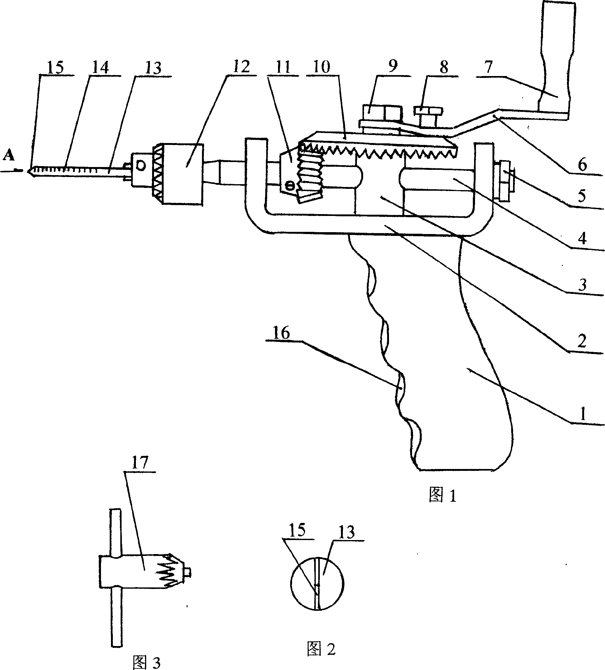
[0011] As shown in the accompanying drawings, the present invention includes a drill body 2, a rocker 7, a shaft 3, a shaft 4, a drill card 12, a drill bit 13 and a pair of bevel gears 10, 11 that mesh with each other. The drill body 2 is arcuate, and a The bevel gears 10 and 11 are arranged on the shafts 3 and 4 which are perpendicular to each other in the drill body 2 respectively. Connected as a whole, the drill card 12 is arranged on the outside of the drill body 2 and is connected with the shaft 4. A handle 1 is provided below the drill body 2. The handle 1 is provided with a finger recess 16. The drill bit 13 is provided with a scale 14, and the drill bit The top drill point 15 of 13 is flat point shape, and the ratio of the number of teeth of bevel gear 10,11 is 3: 1.

[0012] During use, according to the thickness of the scalp and the skull at the drilling position, the drill bit 13 is installed on the drill card 12, the length of the drill bit 13 is adjusted according...


PUM


Abstract

The invention belongs to the medical apparatus technique field, especially relating to a micro-trauma perforator used in neurological clinical surgery, comprising: a drill body (2), a cranked handle (7), a axis (3), a axis (4), a chuck (12), a drill bit (13) and a couple of meshed bevel gears (10) and (11). Wherein, the drill body (2) is in the shape of arch; the bevel gear (10) is mounted on the axis (3) and the bevel gear (11) is mounted on the axis (4) while said two axes are mutually perpendicular mounted in the drill body (2); the bevel gear (1) is integrated to the cranked handle (7) via the handle swinging arm (6), the nut (9) mounted on the swinging arm (6) and the pressing nut (8); the chuck (12) is mounted on the outer side of drill body (2) and connected to the axis (4) as a whole; a handle (1) is arranged under the drill body (2) on which a finger concave (16) is arranged; and a scale (14) is on the drill bit (13) whose top drill point (15) is flat and sharp. The invention has simple structure while it can be used easily and fast with little trauma, therefore, it reduces the suffering of patient. The invention is worth to spread in the application of neurological clinical surgery especially in the salvage of acute disease macroporosity hernia cerebra patient and the patients that needing the surgery of ventricle external conduction.

Description

Technical field [0001] The invention belongs to the technical field of medical instruments, in particular to a minimally invasive cranial drill used in neurosurgery clinical operations. Background technique [0002] In the clinical work of neurosurgery, cranial drilling is often performed for diagnosis and treatment. Commonly used cranial drilling instruments in the art are generally hand drills, pneumatic drills and electric drills, among which the hand-operated type is the most commonly used. Because the ratio of the rotational speed of the drill bit to the handle of the traditional hand-operated cranial drill is 1:1, the drilling speed is slow, the operation is time-consuming and laborious, and the patient's bleeding volume increases, so the patient suffers a lot, especially in emergency treatment. When craniotomy is urgently needed in the critical phase of brain herniation, the rescue time is often delayed due to the complexity of the craniotomy operation, which affects...

Claims


Application Information

Patent Timeline
Patent Type & Authority Applications(China)
IPC IPC(8): A61B17/16
Inventor 张庆林张成曹尚德孙金龙
Owner 张庆林
Learn More