Complex function device, producing method thereof , touch information system and information inputting device
A technology of composite functions and manufacturing methods, which can be used in measurement devices, electrical devices, input/output processes of data processing, etc., and can solve problems such as loss of function and device damage.
- Summary
- Abstract
- Description
- Claims
- Application Information
AI Technical Summary
Problems solved by technology
Method used
Image
Examples
Embodiment approach 1
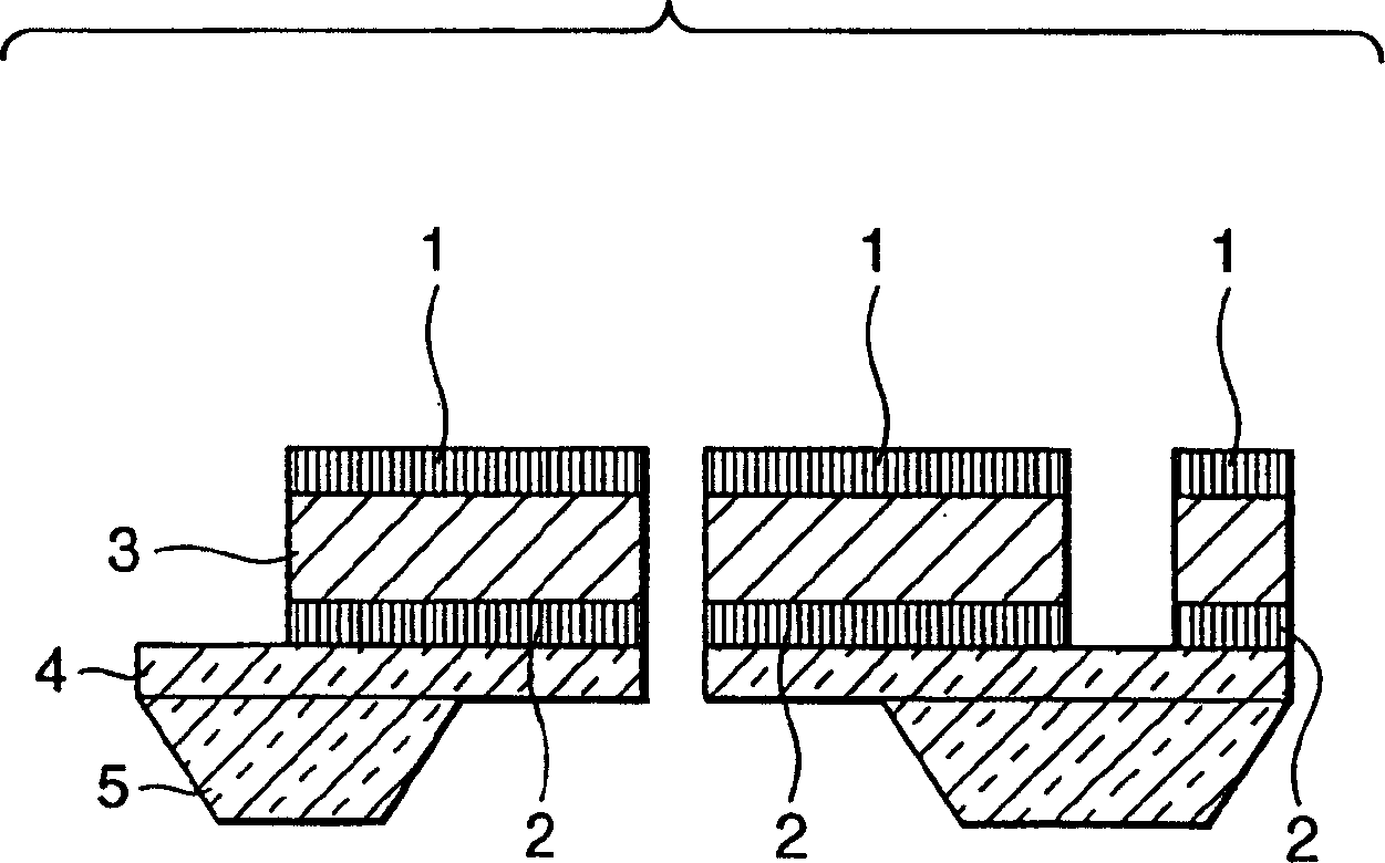
[0049] Use below figure 1 This embodiment will be described.
[0050] exist figure 1 In the tactile information element shown in , 5 is a substrate, which is made of silicon, glass, metal, plastic and other materials. 4 is an elastomer, which is materials such as silicon, glass, metal, plastics. 4 and 5 or 2 and 4 can also use the same material. 3 is a metal oxide, and any composition may be used as long as it is a ferroelectric material or a pyroelectric material. 1 and 2 are electrodes. For convenience, 1 is called the upper electrode, and 2 is called the lower electrode. exist figure 1 Among them, the tactile information unit at the left end, the tactile information unit at the center, and the tactile information unit at the right end respectively detect vertical pressure, horizontal pressure, and temperature, and have the function of reproducing these tactile information.
[0051] In the case where the metal oxide material is used as a ferroelectric material such as ...
Embodiment approach 2
[0066] figure 2 It is a schematic diagram showing the cross-sectional structure of the composite functional element of the present invention. In this embodiment, the metal oxide 3 is mounted on the elastic body 4 with the electrode 2 interposed therebetween. The elastic body may be the same material as the electrode, or may be different. Regardless of the material of the elastic body, the thickness and area of the laminated body of the elastic body of the lower electrode are different from those of the upper electrode, or the Young's modulus is different, and the cantilever beam may be deformed in the vertical direction by an external power source.
[0067] figure 2 The planar structure of the tactile information element is shown in image 3 .
[0068] here image 3 Among them, 6 indicates that four laminates of electrodes / metal oxides / electrodes assembled on cantilever beams intersecting each other at 90° constitute a component, but as long as the electrode / metal oxi...
Embodiment approach 3
[0081] First, use Figure 12 The configuration of the multifunctional device according to Embodiment 3 of the present invention will be described. Figure 12 It is a diagram showing a schematic configuration of a multifunction device according to Embodiment 3 of the present invention.
[0082] 100 is a substrate, which is made of silicon, glass, metal, plastic and other materials. However, in the case of conductive materials such as metals and semiconductors, it is preferable to provide an insulator between the electrodes 130 and 150 in contact with the substrate 100 and the metal oxide material 120 . In addition, in this figure, the electrodes 130 and 150 are separated from each other, but any one of the pair of electrodes may be shared.
[0083] Also, while there is Part B, in Figure 12 It is not described in , when the electrodes 130 and 150 are patterned, there is no problem even if there is electrode material remaining in this part. However, the electrode material re...
PUM
| Property | Measurement | Unit |
|---|---|---|
| thickness | aaaaa | aaaaa |
| thickness | aaaaa | aaaaa |
| thickness | aaaaa | aaaaa |
Abstract
Description
Claims
Application Information
 - R&D Engineer
- R&D Manager
- IP Professional
- Industry Leading Data Capabilities
- Powerful AI technology
- Patent DNA Extraction
Browse by: Latest US Patents, China's latest patents, Technical Efficacy Thesaurus, Application Domain, Technology Topic, Popular Technical Reports.
© 2024 PatSnap. All rights reserved.Legal|Privacy policy|Modern Slavery Act Transparency Statement|Sitemap|About US| Contact US: help@patsnap.com


