Centrifugal pump

A centrifugal pump and pump housing technology, applied in the field of centrifugal pumps, can solve problems such as efficiency effects, and achieve the effects of improving efficiency, increasing volume flow, and improving flow conditions

Inactive Publication Date: 2006-02-01
AWECO APPLIANCE SYST
View PDF2 Cites 10 Cited by
  • Summary
  • Abstract
  • Description
  • Claims
  • Application Information

AI Technical Summary

Problems solved by technology

[0004] In the centrifugal pumps described above, the heating element is arranged on the end side on a cover of the pump housing, thereby creating corresponding restrictions on the design of such pumps, which would have a negative effect on the efficiency of the pump.

Method used


Image

  • Centrifugal pump
  • Centrifugal pump
  • Centrifugal pump

Examples


Embodiment Construction

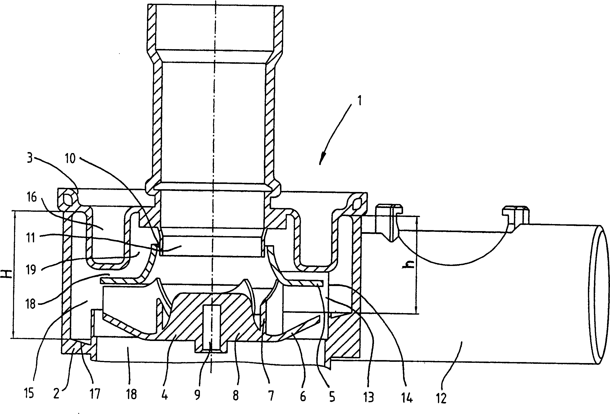
[0029] according to figure 1 The pump 1 includes a cylindrical pump housing 2, on which a cover 3 is mounted. Cover 3 can accommodate figure 1 The heating element is not shown, for which the cover is made of a thermally conductive material, such as metal.

[0030] Arranged within the pump housing 2 is a pump impeller 4 which essentially consists of an upper cover 5 and a lower cover 6 with blades 7 arranged therebetween. The blades 7 are bent and shaped in such a way that, when the pump impeller 4 rotates, a corresponding annular flow of the liquid in the pump impeller 4 results.

[0031] The pump impeller 4 is provided on the underside with an axial projection 8 which has a central bore 9 for receiving a drive shaft, not shown in detail. The pump impeller 4 is thus driven from the side opposite the heating element or cover 3 .

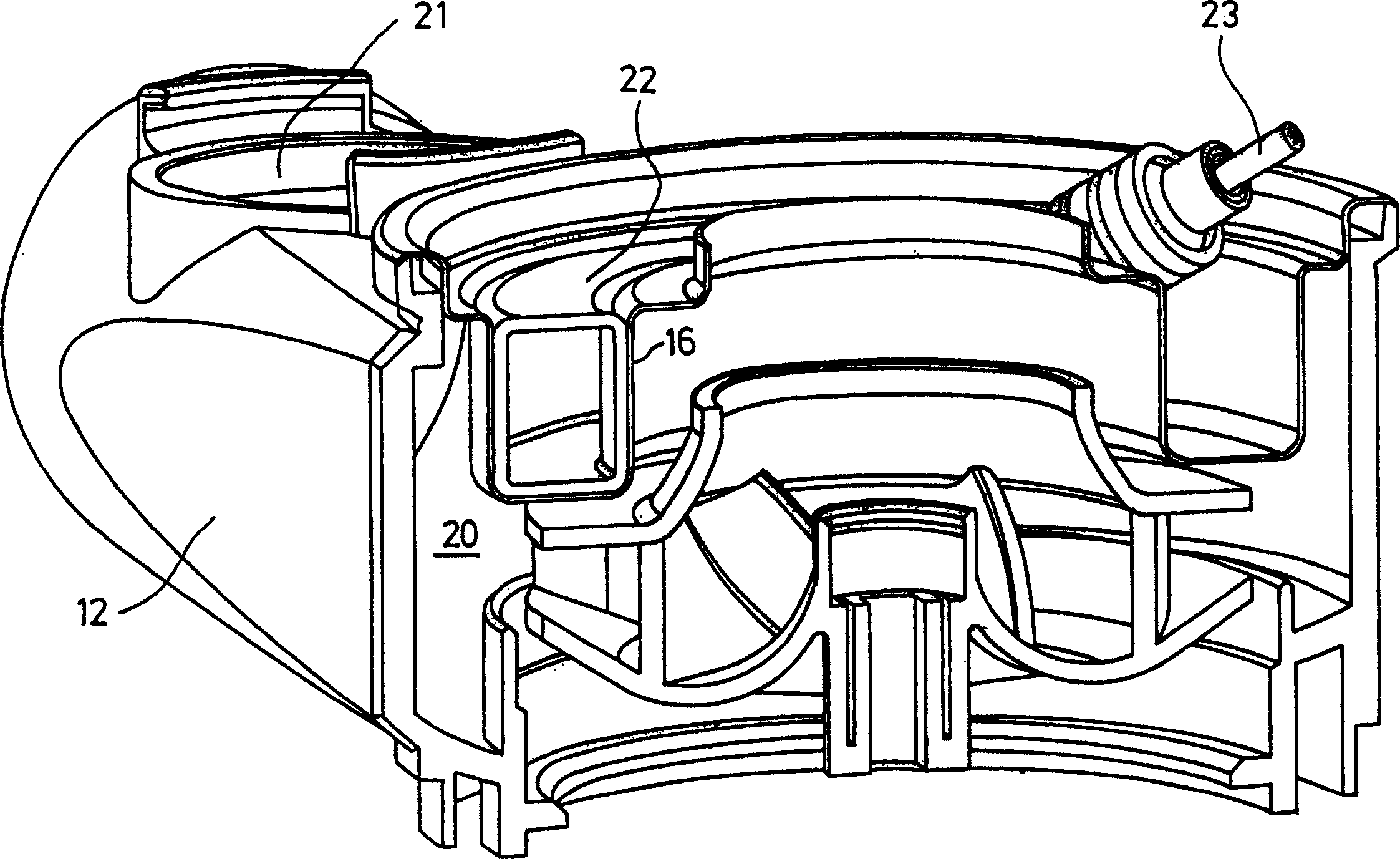
[0032] The upper cover 5 has a central opening 10 into which an inlet connection 11 protrudes. An outlet pipe joint 12 in image 3 Mounted tang...


PUM


Abstract

The invention relates to a centrifugal pump (1), in particular to a centrifugal pump for household appliances, such as washing machines or dishwashers, which comprises a pump housing (2) having an axial inlet (11), an outlet (12) and a heating element, wherein the pump housing (2) incorporates a rotatably mounted impeller (4) and a flow channel (15) enveloping the impeller (4) and heating element. The centrifugal pump (1) according to the invention is intended to have improved efficiency. This is achieved by having the flow cross-section of the flow channel (15) increase along the periphery toward the outlet (12).

Description

technical field [0001] The invention relates to a centrifugal pump / impeller pump according to the preamble of claim 1, in particular a centrifugal pump for domestic machines. Background technique [0002] In domestic machines such as dishwashers or washing machines, a centrifugal pump is usually used to circulate the cleaning fluid. Furthermore, in order to dispense with a separate heating element, centrifugal pumps are known in which the heating element is integrated in the liquid pump (cf. DE 199 16 136). [0003] Furthermore, another known centrifugal pump has a flow channel surrounding the pump impeller and the heating element or its receptacle in the housing cover (cf. DE 103 24 626 A1). [0004] In the aforementioned centrifugal pumps, the heating element is arranged on the end side on a cover of the pump housing, thereby creating corresponding constraints on the design of such pumps, which can have a negative effect on the efficiency of the pump. Contents of the in...

Claims


Application Information

Patent Timeline
IPC IPC(8): F04D29/42A47L15/42D06F39/04D06F39/08F04D29/58
CPCF04D29/586D06F39/085A47L15/4225F04D29/588A47L15/4285F04D29/426D06F39/04
Inventor H-J·克拉夫奇克
Owner AWECO APPLIANCE SYST
Why Eureka
Try Eureka