Vacuum attraction system

A vacuum suction and vacuum technology, applied in the direction of thin material processing, electrical components, electrical components, etc., can solve the problems of increased friction, unstable rotation of the worktable 2, etc., and achieve the effect of stable vacuum degree

Active Publication Date: 2006-01-25
TOKYO WELD CO LTD
View PDF0 Cites 6 Cited by
  • Summary
  • Abstract
  • Description
  • Claims
  • Application Information

AI Technical Summary

Problems solved by technology

Moreover, when the suction force of the workpiece W increases, the frictional force between the workpiece W and the table base 3 increases, or friction occurs between the conveying table 2 and the table base 3 due to air suction, and the rotation of the table 2 tends to increase. become unstable

Method used


Image

  • Vacuum attraction system
  • Vacuum attraction system
  • Vacuum attraction system

Examples


Embodiment Construction

[0033] Hereinafter, embodiments of the present invention will be described with reference to the drawings.

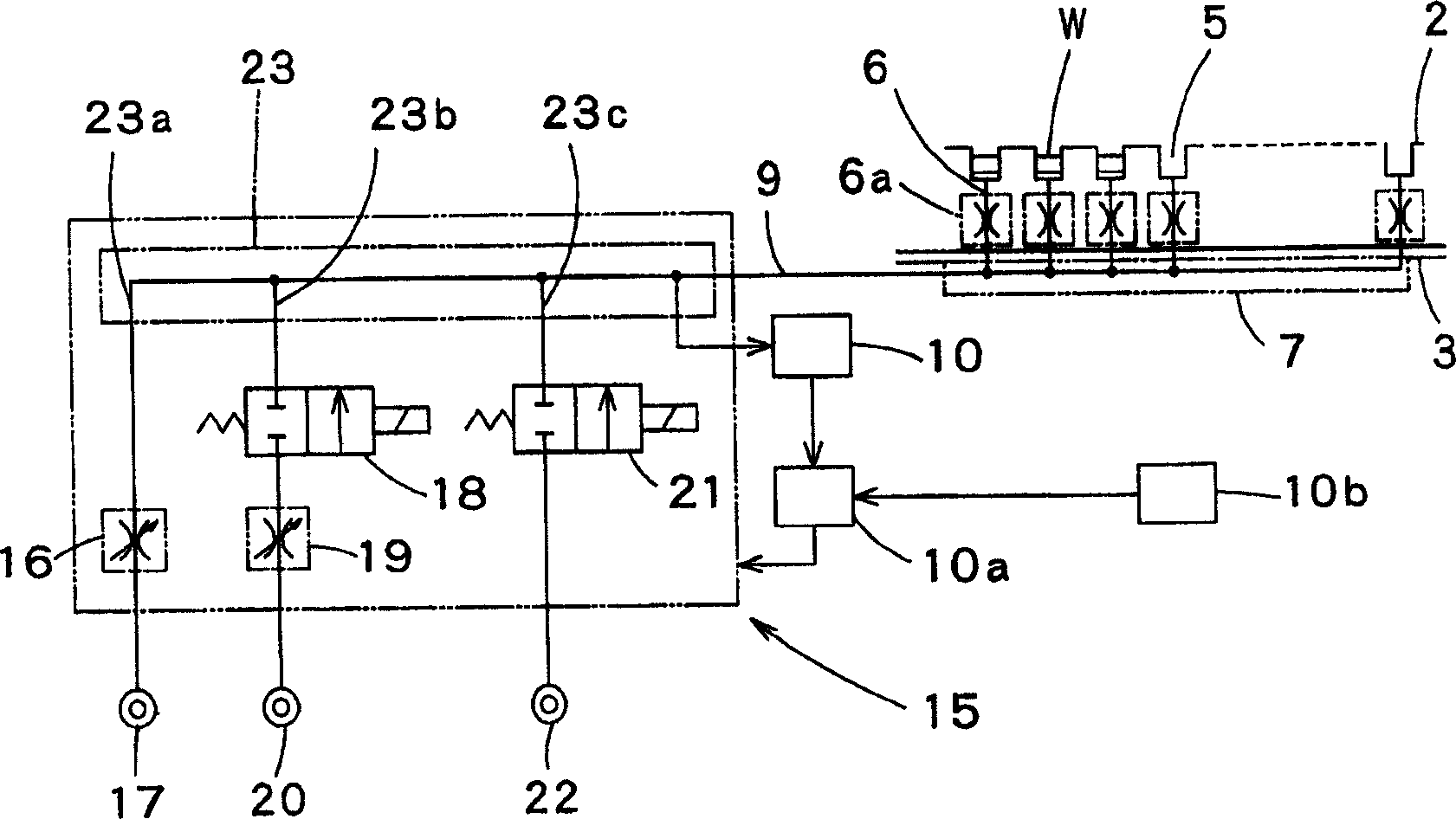
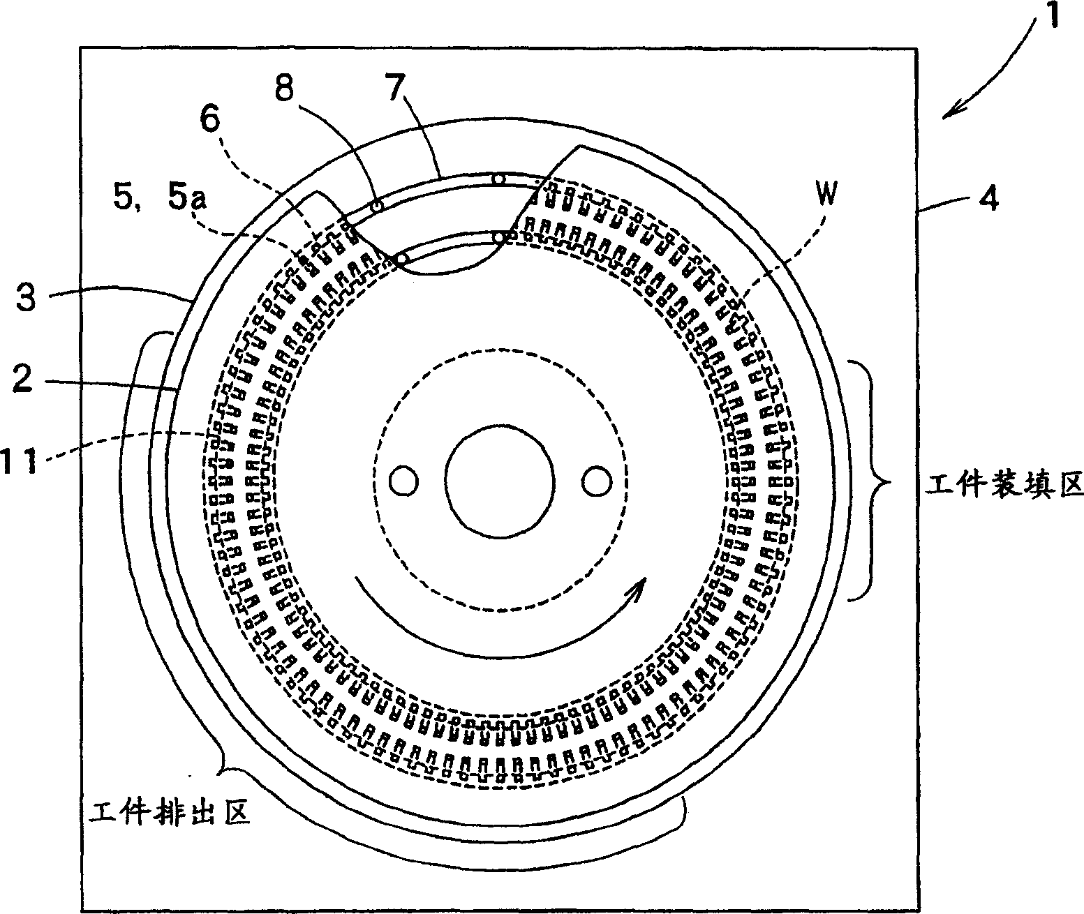
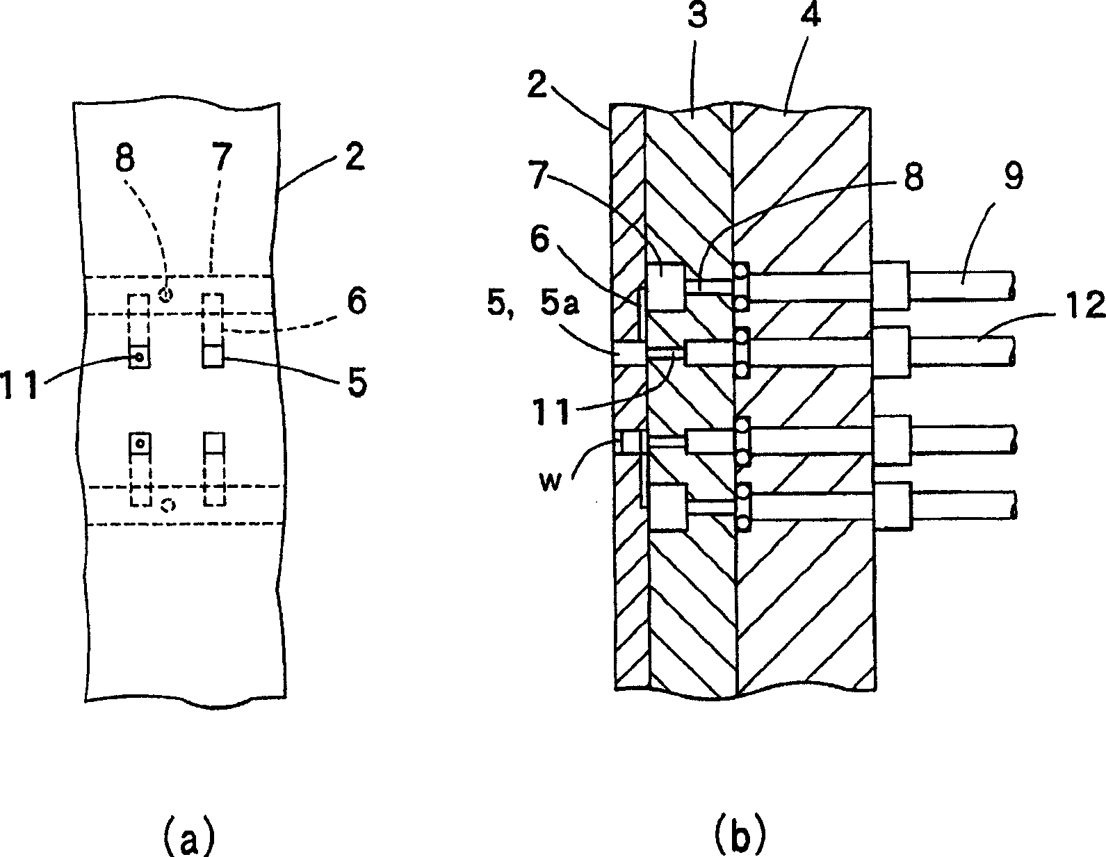
[0034] Figure 1 to Figure 6 It is a figure which shows the vacuum suction system of this invention. in, figure 1 It is a piping diagram showing the vacuum suction system, figure 2 is a plan view showing a workpiece conveying device to which the present invention is applied, image 3 (a) is an enlarged top view of the workpiece conveying device, image 3 (b) is an enlarged side sectional view of the workpiece conveying device, and FIG. 4 is a diagram showing the function of the vacuum suction system of the present invention, Figure 5 It is a graph showing the relationship between the vacuum level and the workpiece filling rate, Figure 6 It is a diagram showing the switching control of the solenoid valve.

[0035] First, according to figure 2 and image 3 A workpiece conveying device to which the present invention is applied will be described.

[0036] fi...


PUM


Abstract

The subject of the invention is to provide a vacuum suction system capable of stably charging a workpiece into a workpiece storing hole of a workpiece carrying table and discharging the workpiece. This system is provided with the workpiece carrying table 2 having the workpiece storing hole 5 and a table base 3 having a vacuum suction groove 7 communicated with the workpiece storing hole 5 of the workpiece carrying table 2. The workpiece storing hole 5 and the vacuum suction groove 7 are communicated with a vacuum generation source 17 via a vacuum pipe 9. A negative pressure sensor 10 is connected to the vacuum pipe 9. Based on a signal from the negative pressure sensor 10, compressed air from a compressed air generation source 20 is delivered to the vacuum pipe 9, or the inside of the vacuum pipe 9 is opened to the atmosphere to regulate a degree of vacuum in the vacuum pipe 9.

Description

technical field [0001] The present invention relates to a vacuum suction system for sucking workpieces of chip components, which are electronic components, into workpiece storage holes of a conveying table. Background technique [0002] according to Figure 8 ~ Figure 10 , to describe a conventional vacuum suction system that sucks a workpiece into a workpiece storage hole of a conveyance table. [0003] in, Figure 8 It is a partial vertical sectional view showing an example of applying a conventional vacuum suction system to a conveyance table, and FIG. 9 is Figure 8 The piping diagram of the vacuum suction system shown, Figure 10 This is a timing chart illustrating the relationship between the workpiece filling rate and the degree of vacuum. [0004] Figure 8 Among them, the conveying table 2 is rotatably provided on a table base 3, and the table base 3 is fixedly provided on a base 4. A plurality of workpiece storage holes 5 are provided in a ring shape through t...

Claims


Application Information

Patent Timeline
Patent Type & Authority Applications(China)
IPC IPC(8): H05K13/02B65G47/91
CPCB65G47/91Y10S414/139
Inventor 小岛智幸吉泽诚二水野显治小平晃久
Owner TOKYO WELD CO LTD
Why Eureka
Try Eureka