Card connector

A plug-in device and transfer technology, which is applied in the direction of two-component connection devices, coupling devices, connections, etc., can solve problems such as difficult repair welding, reduced space for circuit boards, troublesome welding, etc.

Inactive Publication Date: 2006-01-11
JESS-LINK PRODUCTS
View PDF0 Cites 0 Cited by
  • Summary
  • Abstract
  • Description
  • Claims
  • Application Information

AI Technical Summary

Problems solved by technology

[0003] The first common form of the multi-sided single-row, but because the flatness of the welding feet on each side and the coplanarity between the sides are difficult to grasp, it will cause trouble in welding, and it is easy to cause empty welding Or poor contact to form defective products, and even because of too many welding surfaces, the use of circuit board space in electronic products is reduced. Relatively, it is necessary to increase the area of ​​the electronic product circuit board to install electronic parts or circuits, resulting in The electronic product cannot meet the requirements of lightness, thinness, shortness and smallness
[0004] As for the second common form of single-sided multi-row, the soldering legs of the outer row will not have too much problem in welding, but the soldering legs of the inner row are prone to missing soldering because they are located in the inner row, which is even more difficult. Weld the missing weld of the inner row, this defect has been known for a long time
[0005] Even present various card inserting devices are all fixed forms, if because when the electronic card of new specification comes out again, or when wanting to change other combination forms (for example: change the three-in-one form of XD, SD and SM XD, SD and CF three-in-one form), or because a certain electronic card has been eliminated and want to replace it with another, it is necessary to open another mold for additional manufacturing, resulting in an irreducible manufacturing cost. And it is also impossible to achieve a changeable application effect, for example: a certain electronic product is suitable for the three-in-one form of XD, SD and SM, while another electronic product is suitable for the three-in-one form of XD, SD and CF, the difference Only in one of them, the other two are the same, but it cannot replace only one of them in manufacturing, and there are indeed defects that the cost cannot be reduced and cannot be changed

Method used


Image

  • Card connector
  • Card connector
  • Card connector

Examples


Embodiment Construction

[0049] For further understanding of the features and technical content of the present invention, please refer to the following detailed description of the present invention:

[0050] Description and drawings.

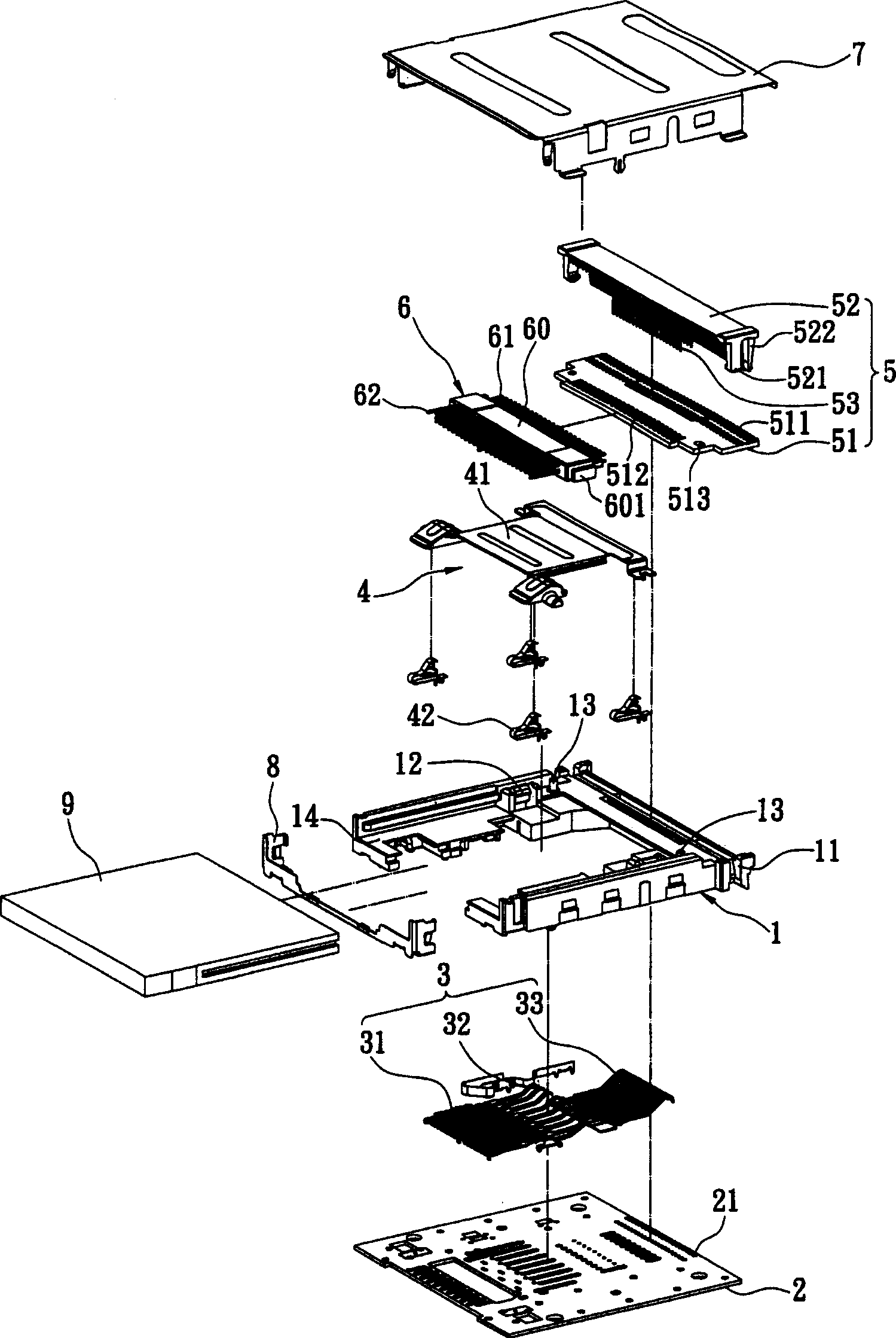
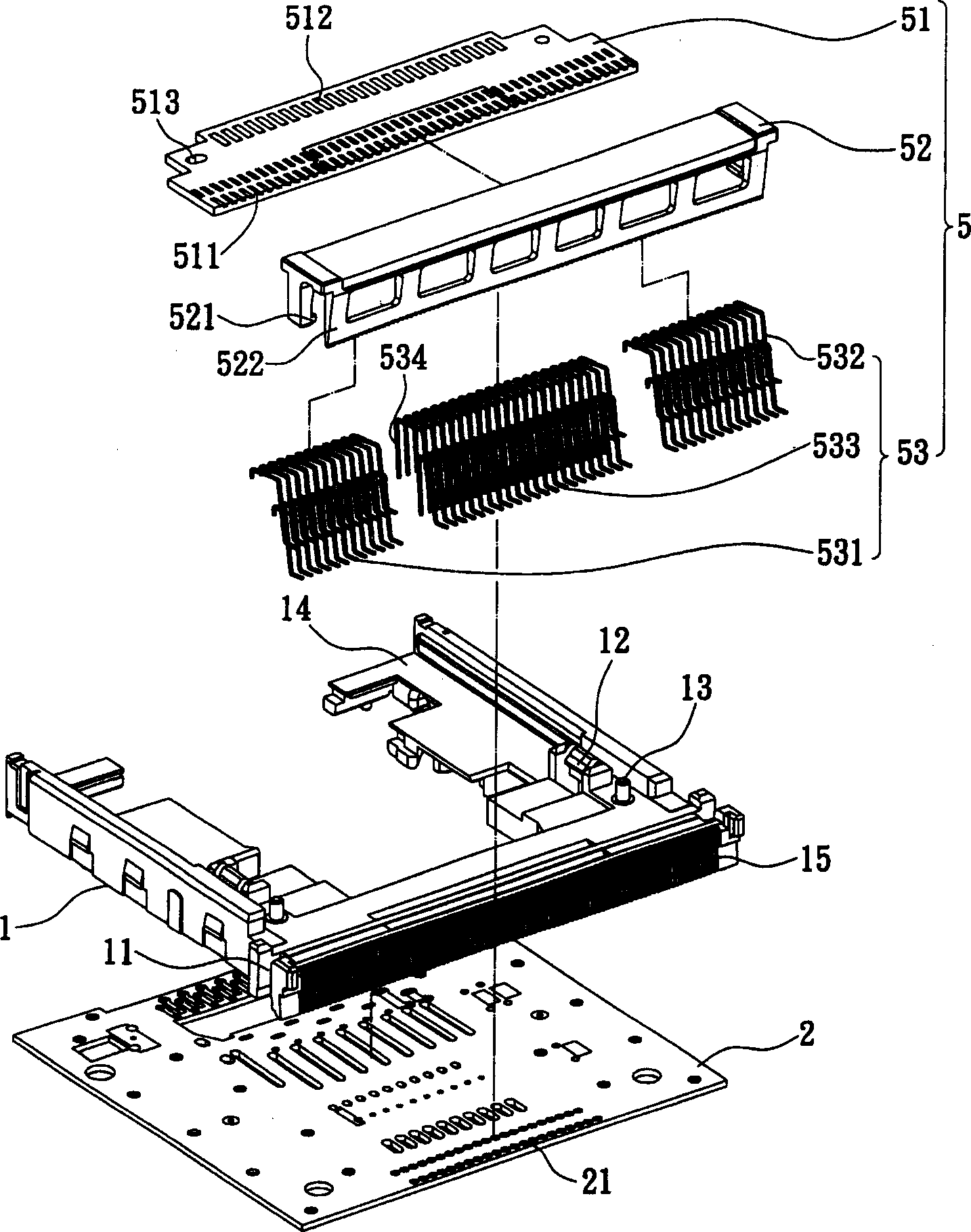
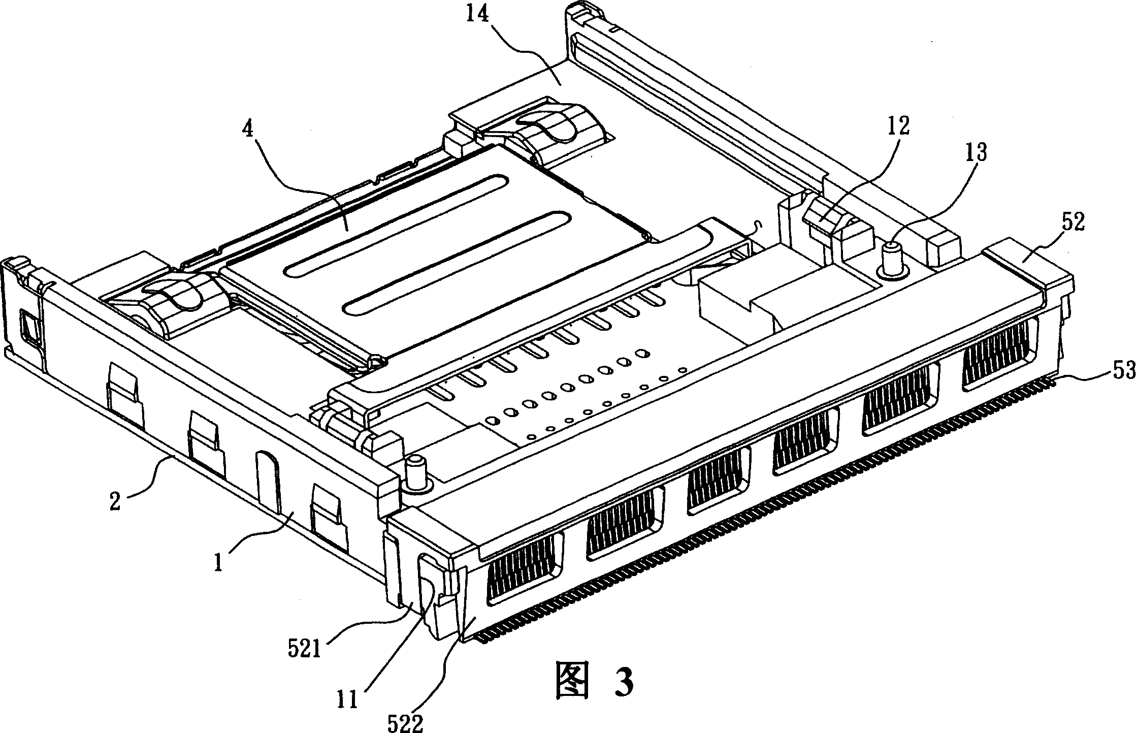
[0051] see figure 1 -- As shown in 6, the present invention provides a card insertion device, in order to insert the electronic card 9 so as to obtain information exchange between the electronic card 9 and an electronic product, the card insertion device is electrically and mechanically connected to the electronic product. The card insertion device includes: an insulating body 1 with a circuit board 2 on the bottom side, a plurality of terminal groups 3, a fool-proof mechanism 4, a connection module 6, a transfer mechanism 5, a metal shell 7, and a front panel8.

[0052] The insulating body 1 is U-shaped with an opening 14, and the rear ends on both sides are respectively provided with a first buckle 11, and the rear side (such as figure 2 shown) is provided with a...


PUM


Abstract

This invention relates to a card pin-contact device including an insulation body with a CB at the bottom side, multiple terminal sets electrically connected on said CB, a connection module including a body positioned on said insulation body, multiple contact terminals and conduction terminals opposite to said body and a transfer unit including a transfer terminal group, a pressing piece positioned on said insulation body to further press on said transfer terminal set and a transfer component positioned on said insulation body and connected with part of the abutting ends of the transfer terminal group and the module, the abutting ends of other part of the transfer terminal group are connected with the welding part of the CB by the transfer piece.

Description

technical field [0001] The present invention relates to a card insertion device, in particular to a device for inserting an electronic card to obtain information exchange between the electronic card and an electronic product, and is required to protrude all the circuit boards on one side and one row. Card connectors with soldered pins. Background technique [0002] The card inserting device is used for inserting the electronic card, so that the electronic card can exchange information with an electronic product. Since there are many types of electronic cards of various specifications and sizes, there is a multi-in-one card connecting device ( Also known as: multi-card connection device) came out. Since the card inserting device must be able to insert various electronic cards, corresponding signal terminal groups must be set inside it so that the first type of electronic card is electrically connected through the first type of signal terminal group, while the second type of ...

Claims


Application Information

Patent Timeline
Patent Type & Authority Applications(China)
IPC IPC(8): H01R24/00H01R12/14H01R12/52H01R12/71
Inventor 陈彦宏
Owner JESS-LINK PRODUCTS
Why Eureka
Try Eureka