Piston internal combustion engine
An internal combustion engine and piston technology, which is applied in the field of four-stroke piston internal combustion engines, can solve the problem of inability to exhaust exhaust gas, and achieve the effects of saving fuel, increasing power, and improving smoke exhaust conditions.
- Summary
- Abstract
- Description
- Claims
- Application Information
AI Technical Summary
Problems solved by technology
Method used
Image


Examples
Embodiment 1
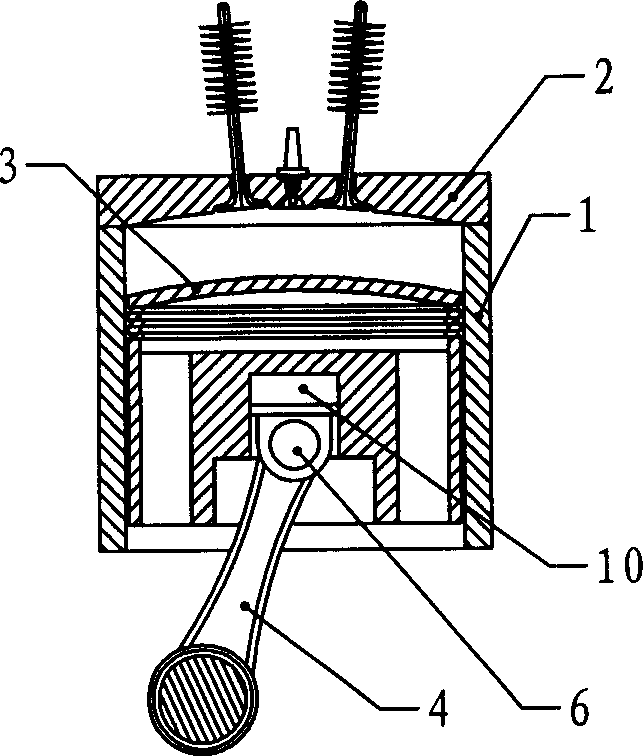
[0015] Embodiment 1: as figure 1 As shown, a piston internal combustion engine includes a cylinder block 1, a cylinder head 2 arranged at the end of the cylinder block 1, a piston 3 and a connecting rod 4 connected to the piston 3, and the stroke distance of the piston 3 relative to the cylinder head 2 is set by the piston 3 Adjust with the variable stroke device between connecting rod 4. The stroke changing device includes an elastic body 5 arranged between the piston 3 and the connecting rod 4, the piston 3 and the connecting rod 4 form an axially movable connection through the cooperation of the connecting pin 6 and the elongated pin groove, and the elastic body 5 is arranged between the connecting pin 6 and the elongated pin groove and the end of the piston 3 facing the cylinder head 2. Generally speaking, the elongated pin groove can be arranged on the piston 3 or on the connecting rod 4 , as long as the thrust direction of the elastic body 5 is to push the piston 3 to t...
Embodiment 2
[0016] Embodiment 2: as figure 2 As shown, the piston internal combustion engine of this embodiment is basically the same as that of Embodiment 1, the difference is that the stroke distance of the piston 3 relative to the cylinder head 2 is adjusted by the variable stroke device arranged between the piston 3 and the connecting rod 4, and the variable stroke The device includes a cylinder-piston pair 10 arranged between the piston 3 and the connecting rod 4 , and the connecting rod 4 and the cylinder-piston pair 10 are connected through a connecting pin 6 . The same purpose and effect as in Embodiment 1 above can be achieved through the elasticity produced by the compression of the medium sealed in the cylinder-piston pair 10 . The medium sealed in the cylinder-piston pair 10 can be air, usable high-temperature-resistant liquid, or the like.
Embodiment 3
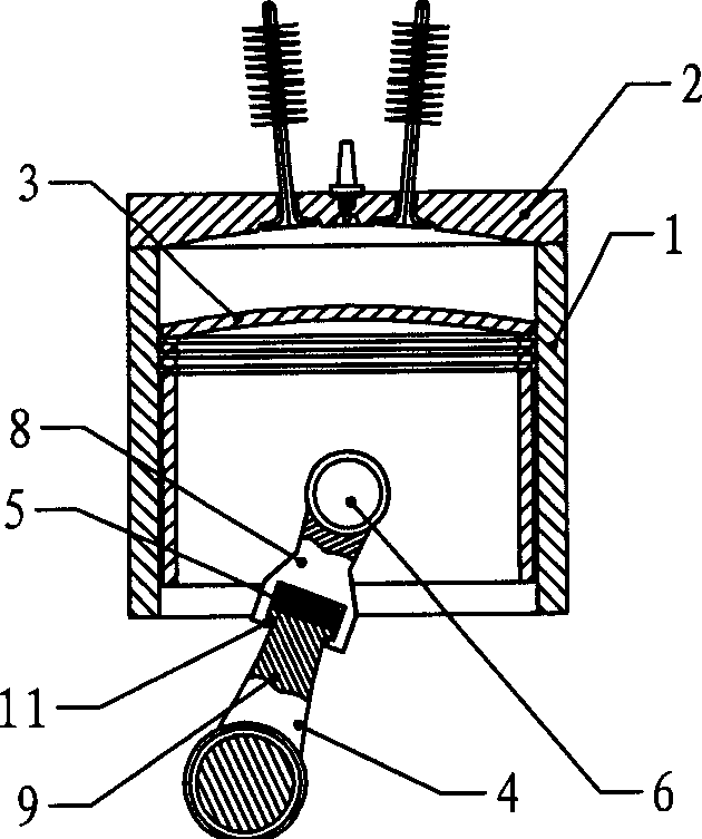
[0017] Embodiment 3: as image 3 As shown, the piston internal combustion engine of this embodiment includes a cylinder block 1, a cylinder head 2 arranged at the end of the cylinder block 1, a piston 3 and a connecting rod 4 connected to the piston 3, and the stroke distance of the piston 3 relative to the cylinder head 2 passes The variable travel device that is arranged on the connecting rod 4 adjusts. The stroke distance of the piston 3 relative to the cylinder head 2 is adjusted by changing the length of the connecting rod 4 at different strokes. The connecting rod 4 is composed of an upper connecting rod 8 and a lower connecting rod 9. The upper connecting rod 8 and the lower connecting rod 9 are slidably connected in the axial direction and are provided with an axial limit structure 11. Between the upper connecting rod 8 and the lower connecting rod 9 An elastic body 5 made of a spring is arranged between them.
PUM
 Abstract
Description
Claims
Application Information
 - R&D
- Intellectual Property
- Life Sciences
- Materials
- Tech Scout
- Unparalleled Data Quality
- Higher Quality Content
- 60% Fewer Hallucinations
Browse by: Latest US Patents, China's latest patents, Technical Efficacy Thesaurus, Application Domain, Technology Topic, Popular Technical Reports.
© 2025 PatSnap. All rights reserved.Legal|Privacy policy|Modern Slavery Act Transparency Statement|Sitemap|About US| Contact US: help@patsnap.com