
Wideband loop antenna

A loop antenna, antenna technology, applied in the direction of loop antenna, antenna, resonant antenna, etc., to achieve the effect of cheap manufacturing cost and good antenna matching

Inactive Publication Date: 2005-12-14
SONY ERICSSON MOBILE COMM AB
View PDF0 Cites 10 Cited by
  • Summary
  • Abstract
  • Description
  • Claims
  • Application Information

AI Technical Summary

Problems solved by technology

[0007] The present invention is to solve the problem of implementing a small antenna which requires only a small ground plane to obtain a defined bandwidth and which provides high efficiency near the human head

Method used


Image

  • Wideband loop antenna
  • Wideband loop antenna
  • Wideband loop antenna

Examples


Embodiment Construction

[0053] A wireless communication device according to the present invention will now be explained. Preferably said wireless communication device is also portable and small. It is also preferred that said device is a headset, which is a preferred variant of the invention. It could also be configured with any other type of small portable communication device than a headset like a non-handheld device, but the invention could equally be provided with any other type of portable communication device, such as a mobile phone or even a common computer. The preferred type of device is for short-range high-frequency wireless communication such as Bluetooth TM device of.

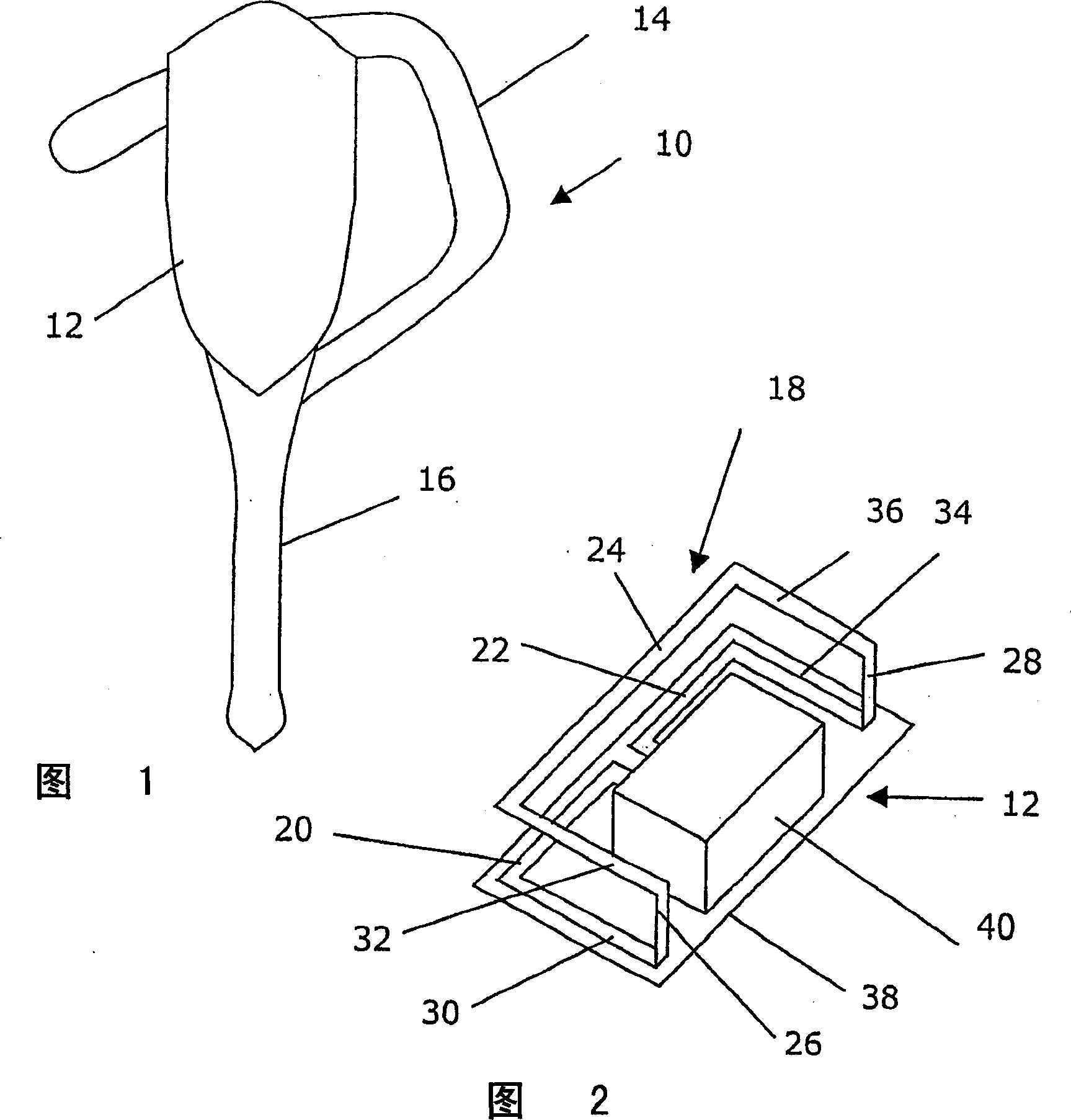
[0054] FIG. 1 shows a schematic view of an earphone 10 including a body 12 , a microphone portion 16 and an ear fastening 14 . The body includes something like the Bluetooth TM Protocol working radio circuitry, batteries and speaker items, all of which are standard for this type of equipment.

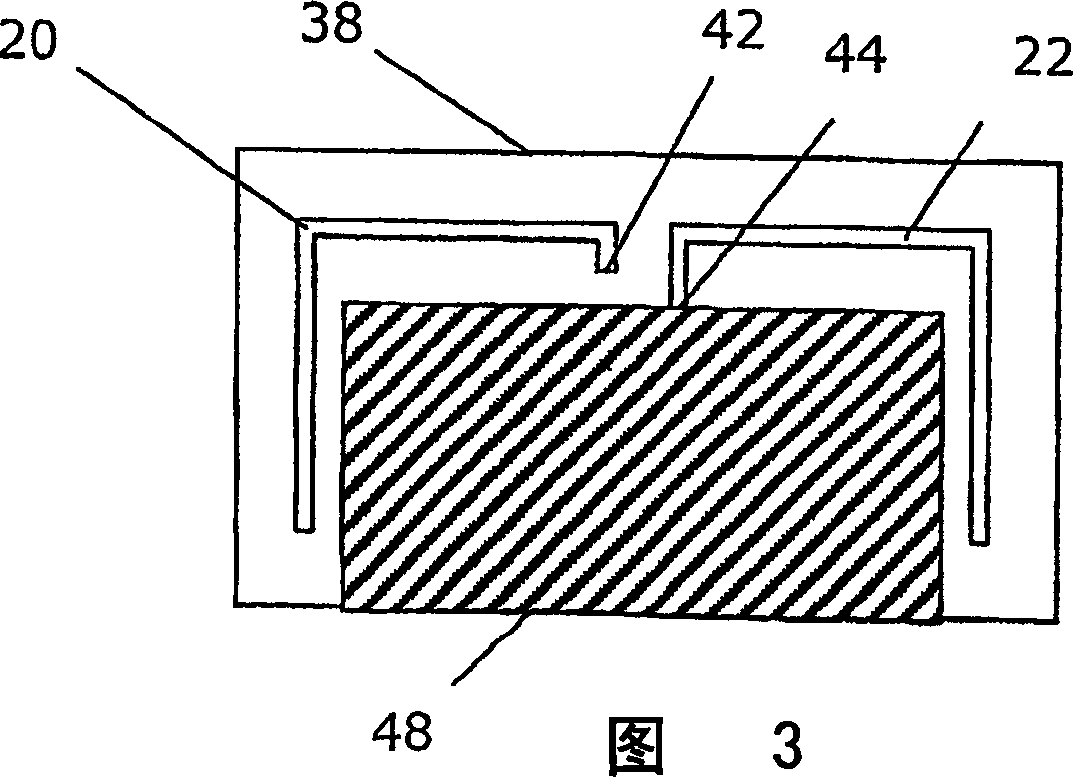
[0055] FIG. 2 shows a ...


PUM


Abstract

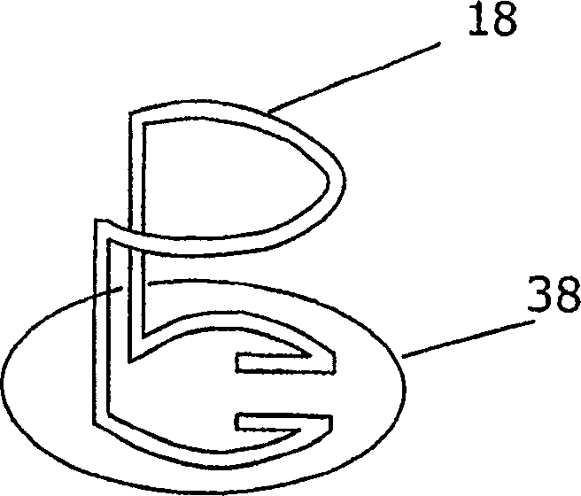
The device has loop antenna element (18) comprising antenna sections (20,22) that are provided in the same plane. The antenna section (24) is provided in another plane parallel to former plane, and the antenna sections (26,28) are provided for interconnecting antenna sections (20,22,24). The antenna sections form a three-dimensional structure with two-dimensional extension in one of the planes. An independent claim is also included for antenna arrangement.

Description

technical field [0001] The present invention relates to the field of antennas, and more particularly, to a wireless communication device including a loop antenna element, and to an antenna device for a wireless communication device. Background technique [0002] Antennas in the field of wireless communication devices, especially such extremely small devices as those used for short-range high-frequency communication, e.g. using Bluetooth TM The antenna in the device of the (Bluetooth) communication protocol has to be small because usually the devices used are small. Standard Bluetooth TM Examples of devices are headsets and hands-free devices that use Bluetooth TM Communicates with, for example, a cellular telephone. So these devices usually need to be small, while at the same time within a certain frequency band and at about 2GHz or higher Bluetooth TM situation can work. [0003] Typical antennas for these types of devices have so far been dipole antennas, monopole ant...

Claims


Application Information

Patent Timeline
Patent Type & Authority Applications(China)
IPC IPC(8): H01Q1/24H01Q7/00H01Q9/26
CPCH01Q1/241H01Q7/00H01Q9/26
Inventor H·罗森伯格H·吉德哈格B·斯文松
Owner SONY ERICSSON MOBILE COMM AB
Learn More