
Automatic control wind sail type swing wing vertical shaft wind motor

A wind turbine and vertical axis technology, which is applied in the field of self-controlled sail-type swing-wing vertical axis wind turbines, can solve problems such as low efficiency, no overspeed protection, and low speed ratio, and achieve high efficiency and low cost

Inactive Publication Date: 2005-11-23
郑衍杲
View PDF0 Cites 10 Cited by
  • Summary
  • Abstract
  • Description
  • Claims
  • Application Information

AI Technical Summary

Problems solved by technology

[0002] The inventor's patent No. has been able to ensure the automatic start of the wind turbine, and maintain the rated speed after reaching the rated wind speed; when encountering a typhoon, the blades will automatically feather, and the wind turbine will be unloaded to ensure safety through the typhoon; the vertical shaft, There is no windward mechanism, the speed-increasing gear and the generator are on the ground, and the maintenance is convenient, so the structure is simple, the weight is light, and the manufacturing cost is very low, but its efficiency is low, and the speed ratio is also low, and its wings and horizontal bars are cantilever beam structures , the bending distance at the root is very large, which requires a bulky structure, and the feathering mechanism cannot ensure that the wings are feathered synchronously, which may cause the wings that are not yet smooth to break first in extremely strong winds, and there is no overspeed protection

Method used


Image

  • Automatic control wind sail type swing wing vertical shaft wind motor
  • Automatic control wind sail type swing wing vertical shaft wind motor
  • Automatic control wind sail type swing wing vertical shaft wind motor

Examples


Embodiment Construction

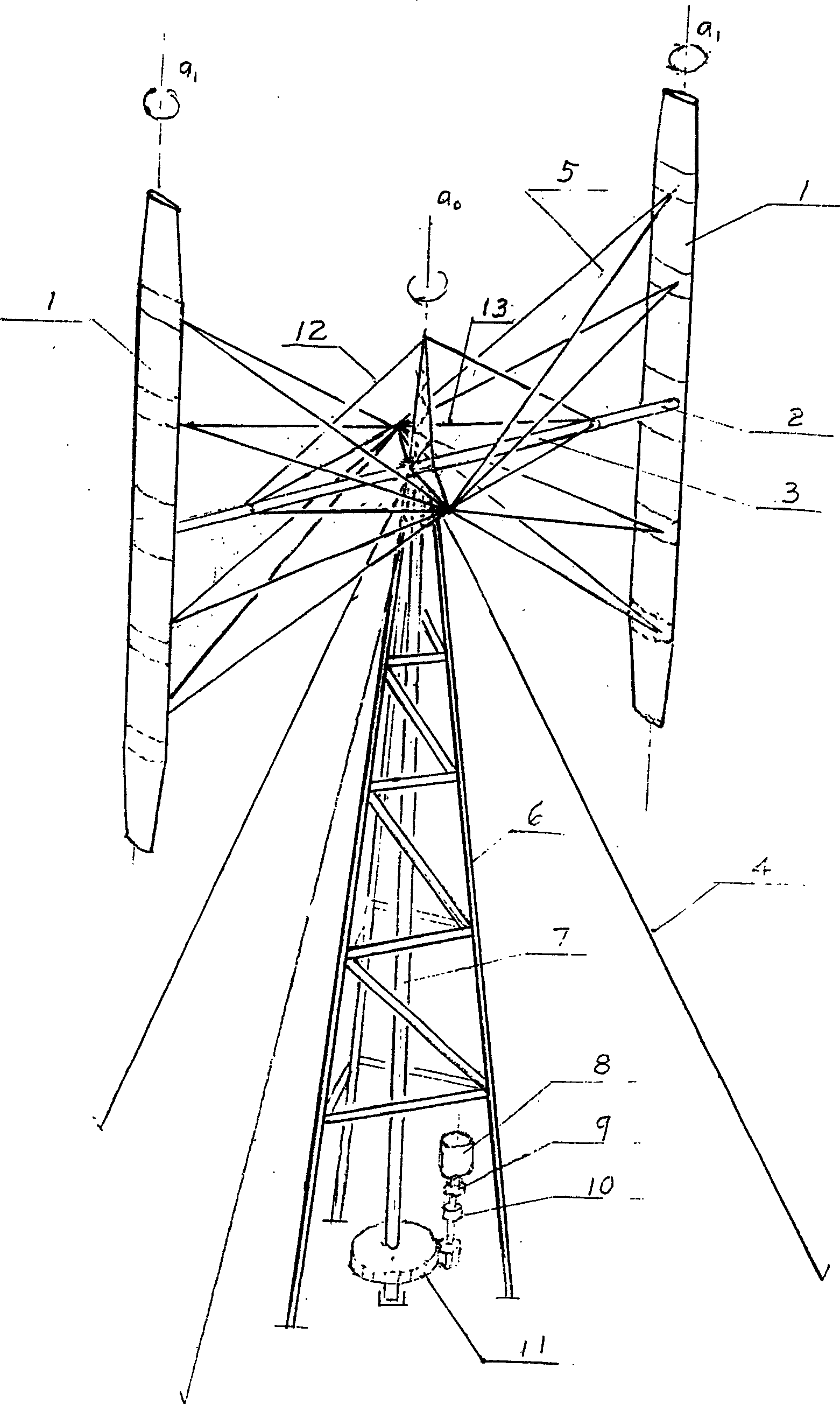
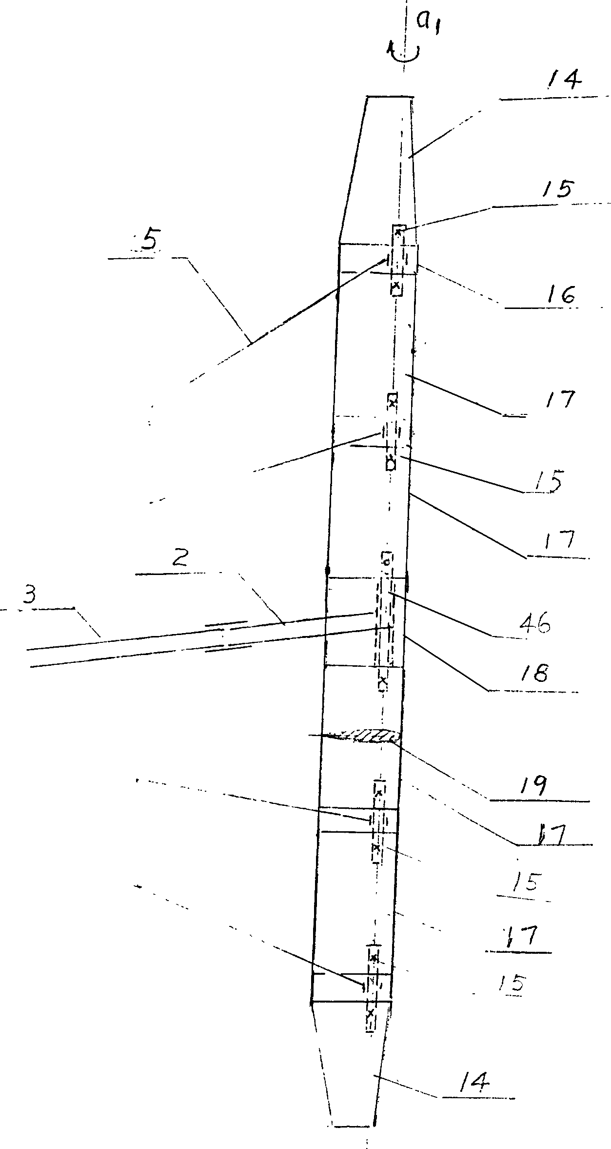
[0025] Accompanying drawing 1 shows general structure of the present invention. One to ten wings 1 are erected at the end of the wing handle 2 at the outer end of the horizontal bar 3 . Horizontal bar 3 is contained in the top of transmission vertical shaft 7. The transmission vertical shaft 7 can rotate around the vertical axis ao of the wind turbine, and its lower end is connected to the speed-increasing gear 11. The output shaft is connected to the centrifugal clutch 10 and then connected to the overrunning clutch 9. The overrunning clutch 9 is connected to the generator 8 on the ground. The transmission vertical shaft 7 uses a truss structure tower Frame 6 supports. The tower 6 is implanted in the ground and its top is pulled from the ground by three or four steel cables 4 . Horizontal bar 3 has oblique steel wire 12 to pull, see accompanying drawing 11 for details. Wing 1 has oblique steel wire 5 to pull, see accompanying drawing 2 for details.

[0026] Accompanying d...


PUM


Abstract

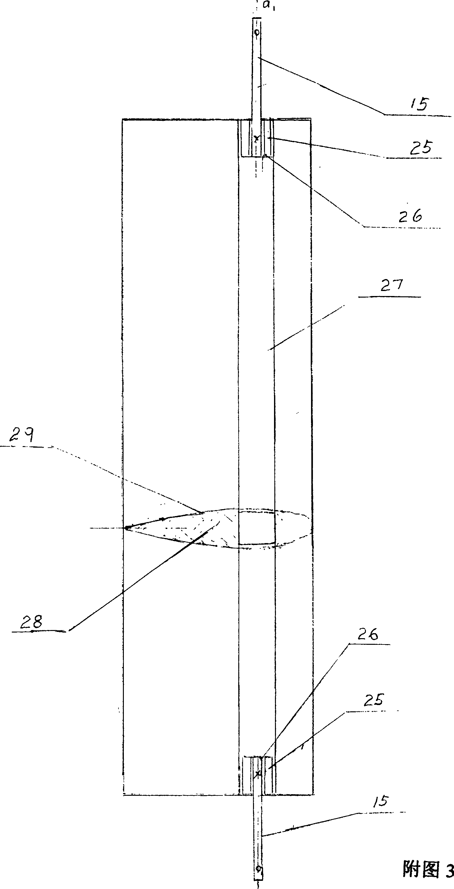
The invention relates to an automatic control sailing wind generator which comprises: wing foil (1), cross bar (3), wing crank (2), driving vertical axis (7), tower (6), generator (8), overriding clutch (9), centrifugal clutch (10), speed increasing gear (11). It is characterized in that the wing foil (1) comprises wing tip (14), wing panel (17), wing segment (16) and wing root (18). In the wing panel installed a feathering mechanism, in the wing root installed a feathering mechanism and swing mechanism; in the wing crank installed a control device and an over speed feathering sensor. The feathering mechanism can ensure the simultaneous feathering and unloading of each wing foil, in the case of over speed or typhoon, the swing mechanism can ensure to start at low speed and smooth speed automatically. The invention also adopts the sloping drawing wire (5) to draw the wing foil (1) and the cross bar (3), the sloping drawing wire (12) and (13) take each cross bar and the steel cable (4) draws the power (6) to the ground to make the system stable.

Description

technical field [0001] The invention relates to a self-controlled sail-type swing-wing vertical-axis wind turbine. Background technique [0002] The inventor's patent No. <98111548.9> has been able to ensure the automatic start of the wind turbine, and maintain the rated speed after reaching the rated wind speed; when encountering a typhoon, the blades will automatically feather, and the wind turbine will be unloaded to ensure safety through the typhoon; the vertical shaft, There is no windward mechanism, the speed-increasing gear and the generator are on the ground, and the maintenance is convenient, so the structure is simple, the weight is light, and the manufacturing cost is very low, but its efficiency is low, and the speed ratio is also low, and its wings and horizontal bars are cantilever beam structures , the bending distance at the root is very large, which requires a bulky structure, and the feathering mechanism cannot ensure that the wings are feathered sync...

Claims


Application Information

Patent Timeline
IPC IPC(8): F03D7/06
CPCF05B2260/72F03D7/06F05B2260/77Y02E10/726F05B2240/14Y02E10/74Y02P70/50
Inventor 郑衍杲
Owner 郑衍杲
Learn More