Nonreciprocal circuit element

A technology of circuit components and components, which is applied in the field of non-reciprocal circuit components, can solve the problems of high cost, large number of components, and inability to miniaturize, etc., and achieve the effects of excellent productivity, small number of components, and improved assembly

Inactive Publication Date: 2005-11-02
ALPS ALPINE CO LTD
View PDF0 Cites 0 Cited by
  • Summary
  • Abstract
  • Description
  • Claims
  • Application Information

AI Technical Summary

Problems solved by technology

[0007] However, conventional non-reciprocal circuit elements require a magnet 52 in addition to a coil 54 in order to change the operating frequency, which not only requires a large number of parts and high cost, but also cannot achieve miniaturization.
[0008] Conventional non-reciprocal circuit elements required a magnet 52 in addition to the coil 54 in order to change the operating frequency, which not only required a large number of parts and high cost, but also had the problem of being unable to achieve miniaturization.

Method used


Image

  • Nonreciprocal circuit element
  • Nonreciprocal circuit element
  • Nonreciprocal circuit element

Examples


Embodiment Construction

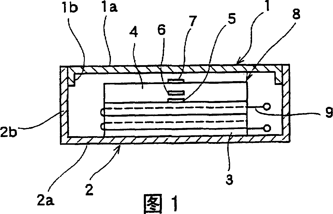
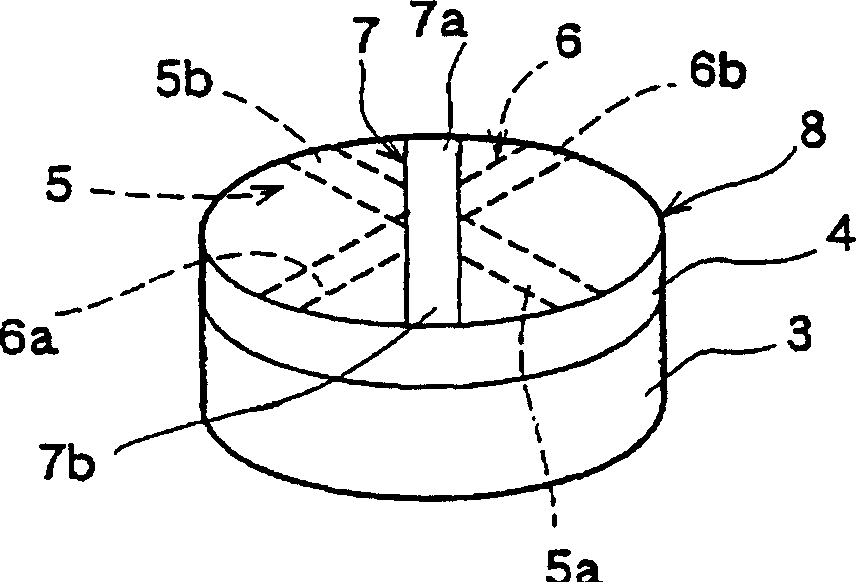
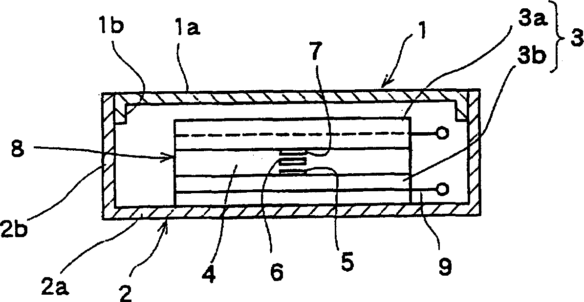
[0029] The non-reciprocal circuit element of the present invention is described, and Fig. 1 is a sectional view of main parts of the first embodiment of the non-reciprocal circuit element of the present invention, figure 2 It is a perspective view of a ferrite component and a dielectric body of the first embodiment of the non-reciprocal circuit element of the present invention, image 3 It is a sectional view of main parts of the second embodiment of the non-reciprocal circuit element of the present invention, Figure 4 It is a perspective view of the ferrite component and the dielectric body of the second embodiment of the non-reciprocal circuit element of the present invention.

[0030] Then, based on Figure 1, figure 2 , to describe the structure of the first embodiment of the non-reciprocal circuit element of the present invention, the first yoke 1 made of magnetic plates (iron plates, etc.) is formed in a box shape or a U shape, and has a square upper plate 1a and a T...


PUM


Abstract

A nonreciprocal circuit element includes a first yoke having an upper plate, a second yoke which has a flat lower plate and forms a magnetic closed circuit together with the first yoke, a flat ferrite member arranged between the upper plate and the lower plate, and first, second and third central conductors arranged to partially cross one another in a vertical direction via a dielectric. The dielectric and the central conductors are arranged on a top surface or a bottom surface of the ferrite member. A coil to which a direct current is applied is arranged at an outer circumference of the ferrite member, such that a direct current magnetic field is generated at the ferrite member by means of the coil. As a result, since a typical magnet is not required, a small nonreciprocal circuit element having the small number of components can be implemented at low cost.

Description

technical field [0001] The present invention relates to a non-reciprocal circuit element composed of an isolator or a circulator used in a transmission unit of a mobile communication device such as a mobile phone. Background technique [0002] Figure 5 is an exploded perspective view of a conventional non-reciprocal circuit element, below, based on Figure 5 The structure of the conventional nonreciprocal circuit element will be described. The first yoke 51 composed of a box-shaped magnetic plate (iron plate) is formed in a box shape and has an upper plate 51a and a convex portion 51b provided on the upper plate 51a. A circular magnet 52 is provided in the first yoke 51 . [0003] The second yoke 53 made of a magnetic plate (such as an iron plate) is formed into a box shape, and is combined with the first yoke 51 to form a closed magnetic circuit. [0004] The coil 54 is provided between the upper plate 51 a and the magnet 52 in a state of being arranged on the outer perip...

Claims


Application Information

Patent Timeline
Patent Type & Authority Applications(China)
IPC IPC(8): H01P1/36H01P1/32H01P1/383H01P1/387
CPCH01P1/387
Inventor 清水祐一
Owner ALPS ALPINE CO LTD
Why Eureka
Try Eureka