
Image processing system, image display apparatus, printer, and printing method

An image display device and image processing technology, applied in printing, printing devices, image communication, etc., can solve the problems of inconsistency in long sides of images, non-addition, etc.

Inactive Publication Date: 2005-11-02
SEIKO EPSON CORP
View PDF2 Cites 7 Cited by
  • Summary
  • Abstract
  • Description
  • Claims
  • Application Information

AI Technical Summary

Problems solved by technology

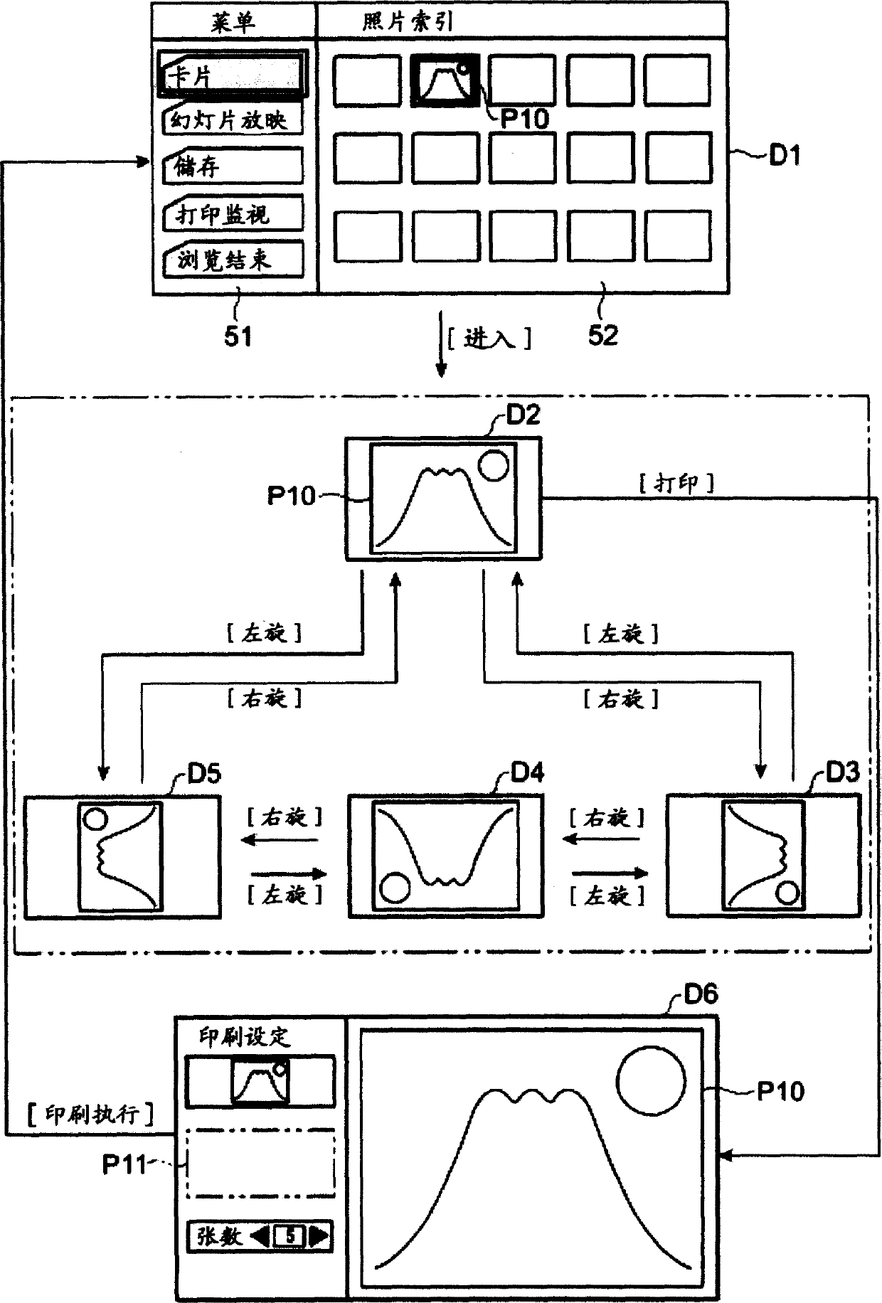
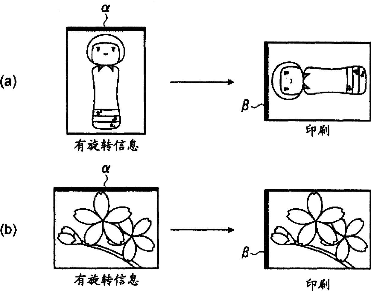
[0007] However, in the prior art, when preparing to print out an image captured by a video camera or an image displayed on a TV screen, no image rotation information (upper position information of a digital camera) is added to the image data or the user may change the image due to image data. When the image data is changed due to rotation, etc., for example, the long side of the image may not match the long side of the printing paper, or the image may be printed upside down.

Method used


Image

  • Image processing system, image display apparatus, printer, and printing method
  • Image processing system, image display apparatus, printer, and printing method
  • Image processing system, image display apparatus, printer, and printing method

Examples


no. 1 Embodiment approach

[0046] Hereinafter, a first embodiment for realizing the present invention will be described.

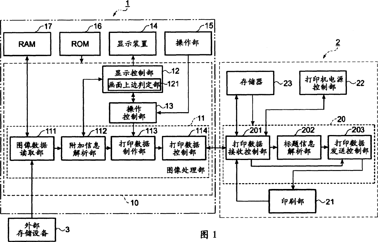
[0047] FIG. 1 is a block diagram showing a schematic configuration of an image processing system of the present invention.

[0048] In FIG. 1 , the image processing system is composed of an image display device 1 , a printer 2 as a printing device, and an external storage device 3 . And, in the external storage device 3, for example, various drive devices such as CD-R / RW (Compact Disk Recordable / ReWritable storable disc / rewritable disc), DVD, HD (Hard Disk hard disk), digital cameras, Notebook PC (Personal Computer), or, for example, various card media (chip media) read / write devices storing image data of digital cameras and the like.

[0049] The image display device 1 is constituted by a CPU (Central Processing Unit) 10 , a display device 14 , an operation unit 15 , a ROM 16 , and a RAM 17 . Furthermore, when the CPU 10 executes the control program and various application progra...

no. 2 Embodiment approach

[0097] Hereinafter, the second embodiment will be described.

[0098] The second embodiment is an embodiment in which an image display device 100 incorporating a television receiving function is configured as an image display device constituting an image processing system. That is, in the second embodiment, as shown in FIG. 9 , it has the same components as those in the above-mentioned first embodiment except for the components (antenna 30, TV tuner 31, and capture unit 32) that are provided with the TV receiving function. In the basic configuration, the same symbols are assigned to the parts corresponding to those in FIG. 1 , and detailed description thereof will be omitted. In addition, the configuration and operation other than the television reception function are the same as those of the first embodiment, and the description thereof will also be omitted.

[0099] Fig. 9 is a block diagram showing a schematic configuration of an image processing system according to a seco...

example 1

[0112] In the first embodiment, the case where the external storage device 3 (cardmedia read / write device storing image data of a digital camera) is connected to the image display device 1 has been described. However, it may be an image display device that incorporates a television reception function and connects an external storage device 3 .


PUM


Abstract

Exemplary embodiments of the invention provide an image processing system, an image display apparatus, a printer, and a printing method that are capable of, when a user attempts to print-output image data, adjusting an orientation of printing of the image data and an orientation of a print sheet to an appropriate direction to print-output the image data on the print sheet. According to exemplary embodiments, an image display apparatus includes a display device and a display control unit that controls to display an image on the display device on the basis of image data to be inputted. A printer includes a printing unit that outputs an image based on the image data to a print medium and an image upper side judging unit that, in printing the image displayed on the display device, judges the top and the bottom of the image on the basis of additional information included in image data of the image. The printer rotates the image such that an upper side of the image and an upper side of the print media defined by the printer coincide with each other on the basis of a result of the judgment by the image upper side judging unit and outputs the image to the printing unit.

Description

technical field [0001] The present invention relates to an image processing system, an image display device, a printer, and a printing method. The image processing system includes an image display device for processing image data and a printer for outputting the image data to a printing medium. Background technique [0002] In the past, the following image processing equipment and image printing equipment have been proposed, which can be used to store and print TV images, DVD (Digital Versatile Disc, Digital Versatile Disc) reproduced images, and images captured by video cameras. Such devices, for example, video printers and television receivers and DVD reproducing devices with video input capabilities are well known. [0003] As the above-mentioned television receiver is well known, the above-mentioned television receiver is used to convert the television signal into image data and store it sequentially in the video storage unit. If a printout instruction is input through t...

Claims


Application Information

Patent Timeline
IPC IPC(8): B41J21/00G06F3/12G06F15/00H04N1/387
CPCH04N1/00278H04N2201/3278H04N2201/0087H04N2201/0082H04N2201/3216H04N1/32128H04N1/00347H04N1/3877H04N2201/3215H04N1/00294H04N2201/3254H04N2201/3214H04N2201/3242H04N2201/0084H04N2201/0089
Inventor 中村康浩
Owner SEIKO EPSON CORP
Learn More