Scanning miniature optical probes with optical distortion correction and rotational control
A technology of optical probes and light beams, applied in the direction of optics, optical components, optical devices, etc., can solve the problem that the fluid cannot be in contact with the imaging tip
- Summary
- Abstract
- Description
- Claims
- Application Information
AI Technical Summary
Problems solved by technology
Method used
Image
Examples
Embodiment Construction
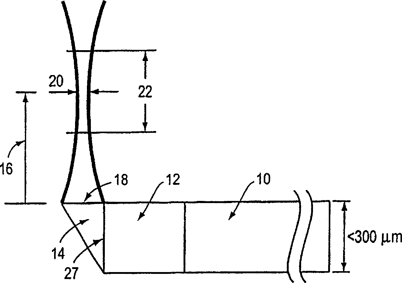
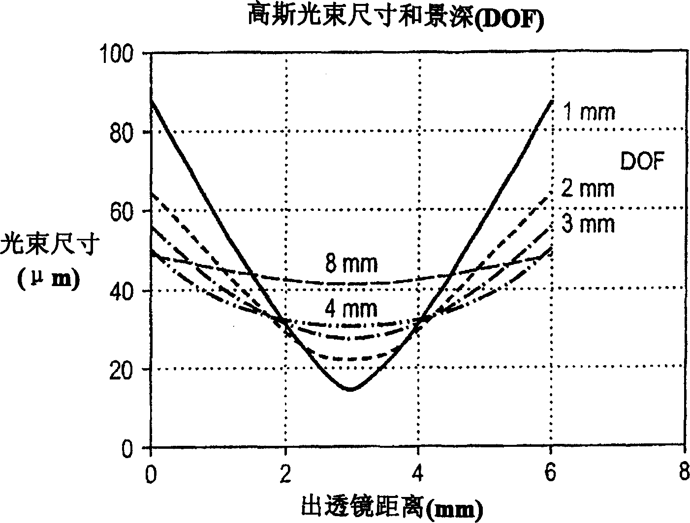
[0025] figure 1 An example of an imaging lens embodiment is shown. In this embodiment, a single mode fiber 10 is bonded or fixed to the lens 12 . The lens 12 has approximately the same diameter as the fiber 10 . Fiber 10 includes several different thin protective coatings. The beam directing means 14, in this embodiment a 45 degree (or other suitable angle) folded mirror, is attached to the lens 12 using fusion bonding or glue. The folding mirror 14 can be coated with a high reflectance material or operate on the principle of total internal reflection. about figure 1 As shown, in the illustrated embodiment, the length of the working distance 16 of the lens 12 is from the surface 18 of the fold mirror 14 to the waist position 20 of the Gaussian beam. The combination of lens 12 and beam directing element 14 amplifies (or reduces) the beam waist originally located at the exit of single-mode fiber 10 and creates a new beam waist 20 at a circular spot located at working distan...
PUM
 Abstract
Description
Claims
Application Information
 - R&D
- Intellectual Property
- Life Sciences
- Materials
- Tech Scout
- Unparalleled Data Quality
- Higher Quality Content
- 60% Fewer Hallucinations
Browse by: Latest US Patents, China's latest patents, Technical Efficacy Thesaurus, Application Domain, Technology Topic, Popular Technical Reports.
© 2025 PatSnap. All rights reserved.Legal|Privacy policy|Modern Slavery Act Transparency Statement|Sitemap|About US| Contact US: help@patsnap.com


