Self-suction rotary liquid spraying pump

A self-priming, liquid technology, applied in the direction of non-variable pumps, non-displacement pumps, pumps, etc., can solve the problems that the suction/lifting of liquid cannot be realized, and the suction impeller cannot effectively suck liquid, etc.

Inactive Publication Date: 2005-10-12
郑俊礼
View PDF0 Cites 0 Cited by
  • Summary
  • Abstract
  • Description
  • Claims
  • Application Information

AI Technical Summary

Problems solved by technology

Further experiments have shown that when the rotational speed of the absorbed liquid outside the liquid suction impeller is consistent with or higher than that of the liquid suction impeller, the liquid suction impeller cannot effectively suck the liquid, that is, it cannot achieve suction. / Promote the purpose and function of liquid

Method used


Image

  • Self-suction rotary liquid spraying pump

Examples


Embodiment Construction

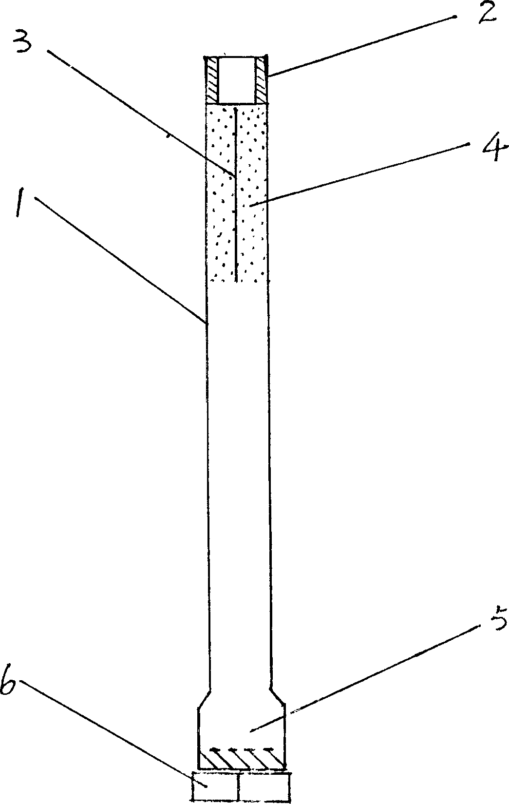
[0009] In the figure, one end of the straight pipe (1) is concentrically connected with a shaft connector (2). As shown in this illustration, it is in the shape of a self-tightening inner thread, and the inner thread is connected with an external power shaft configured separately. The outer threaded buckle is connected concentrically. The straight pipe (1) is in the shape of a concentric circular pipe body, and a plurality of small spray holes are evenly opened around the upper part of the pipe body to form a spray hole section (4), corresponding to the height of the spray hole section (4) in the lumen , a group of concentrically fixed core plates (3), shown as a straight plate structure in this illustration. The distraction plate (3) evenly separates the inner cavity of the straight pipe and makes it into a shape of up and down diameters, and the distraction plate (3) is composed of a straight plate passing through the center / several straight plates evenly distributed and con...


PUM


Abstract

This invention is a self-inhale pump of rotating sprinkler. On the top of a straight tube installs a joint coupling. To the top of the tube is a belt of multi holes, correspondingly in the center of the tube installs a board. On the bottom of the tube installs a turbine which is put under water at working. This pump is fixed to a driving axis.

Description

technical field [0001] The invention relates to a centrifugal water pump device, in particular to a self-priming liquid spin sprinkler pump. Background technique [0002] According to experiments and observations, all centrifugal pumps for pumping liquid, when the water-absorbing impeller sucks liquid during work, will drive the liquid / fluid flowing close to the impeller into a vortex shape, and during the process of this phenomenon , the closer the liquid is to the suction impeller, the faster it rotates, which forms a physical vortex. Further experiments have shown that when the rotational speed of the absorbed liquid outside the liquid suction impeller is consistent with or higher than that of the liquid suction impeller, the liquid suction impeller cannot effectively suck the liquid, that is, it cannot achieve suction. / Promote the purpose and function of the liquid. Therefore, we assume that making full use of the characteristic effect of this physical phenomenon wil...

Claims


Application Information

Patent Timeline
Patent Type & Authority Applications(China)
IPC IPC(8): F04D1/00F04D9/02
Inventor 郑俊礼
Owner 郑俊礼
Why Eureka
Try Eureka