Optical system
An optical system and optical surface technology, applied in the field of optical systems, can solve the problems of weakened anti-reflection film, increased reflected light, and higher risk of ghosting and halos, and achieves the effect of suppressing ghosting and halos, and suppressing Produces, low reflectivity effect
- Summary
- Abstract
- Description
- Claims
- Application Information
AI Technical Summary
Problems solved by technology
Method used
Image


Examples
no. 1 example
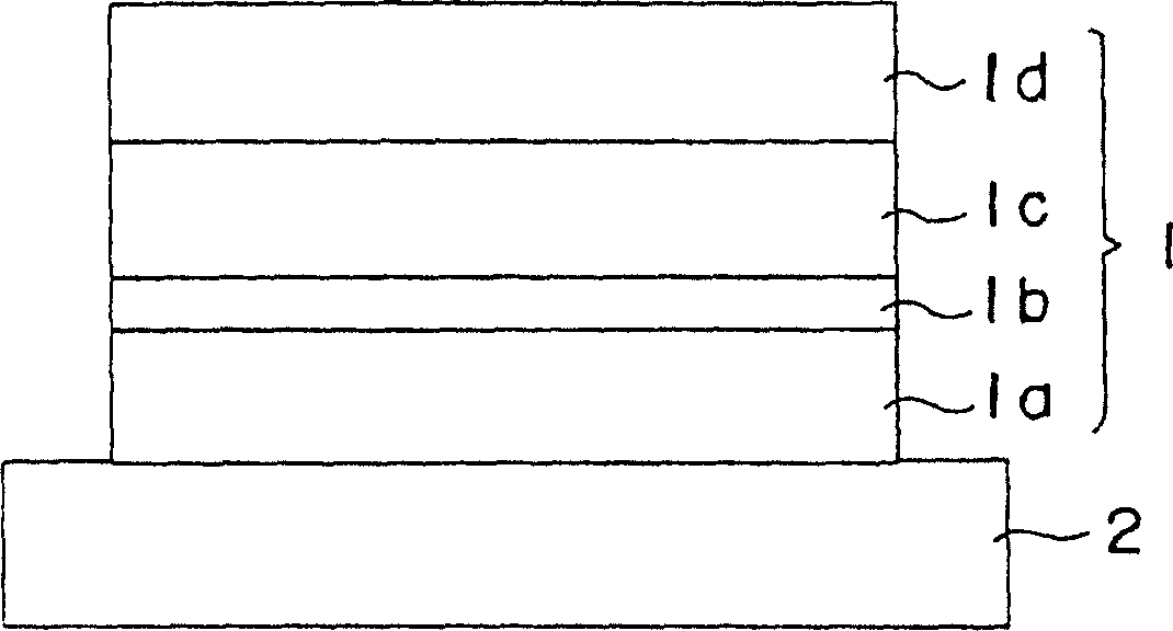
[0033] Next, referring to FIG. 3 , as a first embodiment, an imaging optical system 10 will be described as an optical system having an optical element on which the above-mentioned antireflection film 1 is formed. This imaging optical system 10 is used as a zoom lens for a video camera whose focal length continuously changes from 18mm to 35mm, and consists of a parallel plane plate F serving as a protective glass, a negative meniscus lens L1 with a convex surface facing the object side, and a convex surface facing the object side. A combination lens in which the negative meniscus lens L2 on the object side and the negative meniscus lens L3 with the convex surface facing the Combination lens with convex lens L7 attached together, aperture stop P, combination lens with biconvex lens L8 and biconcave lens L9 bonded together, combination lens with negative meniscus lens L10 and biconvex lens L11 with the convex surface facing the object side bonded together , and a biconvex lens L...
no. 2 example
[0071] Figure 4 An imaging optical system 20 as a second embodiment of the present invention is shown. The imaging optical system 20 is a camera lens with a focal length of 14 mm, and consists of a negative meniscus lens L1 with a convex surface facing the object side, a positive meniscus lens L2 with a convex surface facing the object side, and a negative meniscus lens L2 with a convex surface facing the object side. Lunar lens L3, a combination lens in which a negative meniscus lens L4 with a convex surface facing the object side and a negative meniscus lens L5 with a convex surface facing the object side are bonded together, a negative meniscus lens L6 with a convex surface facing the object side, biconvex lens L7, the combination lens of the negative meniscus lens L8 with the convex surface facing the object side and the biconvex lens L9 pasted together, the biconcave lens L10, the aperture diaphragm P, and the biconvex lens L11 and the meniscus lens L12 with the concave ...
no. 3 example
[0117] Second, referring to Figure 5 and Figure 6 , as a third embodiment, an imaging optical system 30 will be described as an optical system having an optical element on which the above-mentioned antireflection film 1 is formed. This imaging optical system 30 is used as a lens for a camera with a focal length of 293.798 mm, and consists of a parallel plane plate F1 serving as a cover glass, a biconvex lens L1, a joint lens in which a biconvex lens L2 and a biconcave lens L3 are pasted together, in order from the object side, A combination lens in which a negative meniscus lens L4 with a convex surface facing the object side and a biconvex lens L5 are bonded together, a biconcave lens L6, a combination lens in which a positive meniscus lens L7 with a concave surface facing the object side and a biconcave lens L8 are bonded together, Aperture diaphragm P, biconvex lens L9, negative meniscus lens L10 with concave surface facing the object side, positive meniscus lens L11 with ...
PUM
| Property | Measurement | Unit |
|---|---|---|
| reflectivity | aaaaa | aaaaa |
| reflectivity | aaaaa | aaaaa |
| angle of incidence | aaaaa | aaaaa |
Abstract
Description
Claims
Application Information
 - Generate Ideas
- Intellectual Property
- Life Sciences
- Materials
- Tech Scout
- Unparalleled Data Quality
- Higher Quality Content
- 60% Fewer Hallucinations
Browse by: Latest US Patents, China's latest patents, Technical Efficacy Thesaurus, Application Domain, Technology Topic, Popular Technical Reports.
© 2025 PatSnap. All rights reserved.Legal|Privacy policy|Modern Slavery Act Transparency Statement|Sitemap|About US| Contact US: help@patsnap.com