
Lining structure of aluminium electrolytic bath

An aluminum electrolytic cell and electrolytic cell technology, applied in the field of aluminum electrolytic cell lining structure, can solve problems such as side carbon block pressure plate deformation, liquid electrolyte infiltration, poor heat dissipation, etc., to achieve extended service life, good heat balance, increased The effect of large cooling area

Inactive Publication Date: 2005-09-21
SHENYANG ALUMINIUM MAGNESIUM INSTITUTE
View PDF1 Cites 19 Cited by
  • Summary
  • Abstract
  • Description
  • Claims
  • Application Information

AI Technical Summary

Problems solved by technology

At present, the anti-seepage layer under the cathode carbon block group of the electrolytic cell lining structure in the prior art mostly adopts powdery dry anti-seepage material, which has good electrolyte permeability resistance, but it needs a special machine for high-frequency vibration during construction. Compaction; light or heavy castables are used around the cathode carbon block, which contains a certain amount of water. After the water evaporates, there are tiny gaps, which cause the infiltration of liquid electrolyte; after the normal production of the electrolytic cell, the side carbon block is upward Arching, causing deformation of the pressure plates on the side carbon blocks
The height of the artificial legs of the existing electrolytic tank chamber is at the junction of the aluminum liquid and the electrolyte liquid, so that the side carbon blocks are directly washed by the interface fluctuations of the electrolyte liquid and the aluminum liquid; , not suitable for the large-scale prebaked anode electrolyzer production process to complete the self-extinguishing effect requirements, and the heat dissipation effect is not good

Method used


Image

  • Lining structure of aluminium electrolytic bath

Examples


Embodiment 1

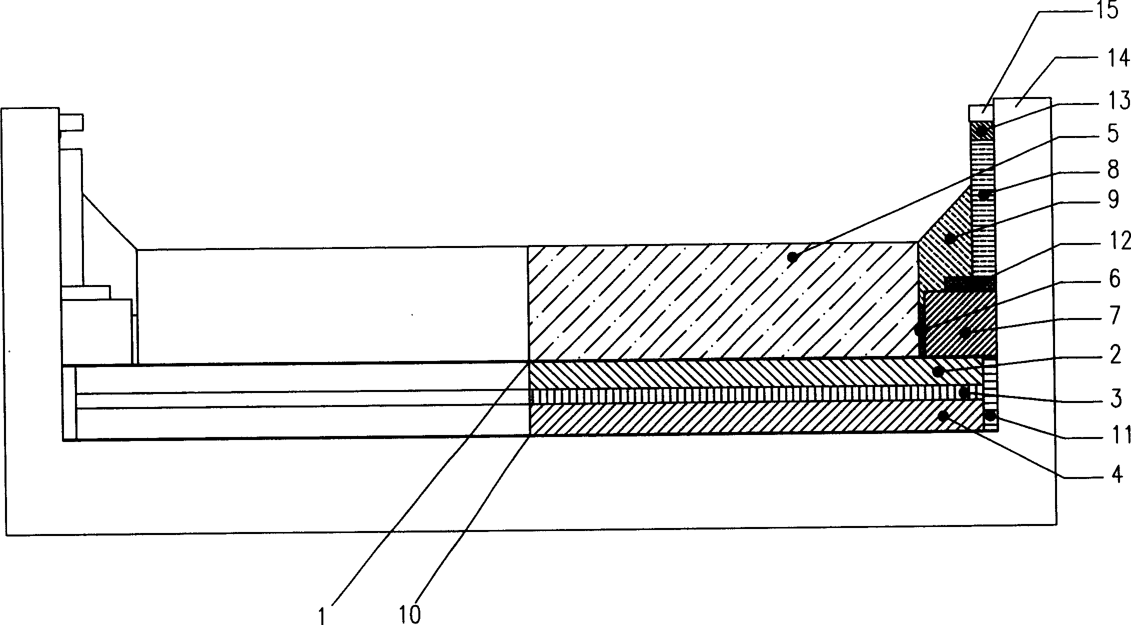
[0019] An aluminum electrolytic cell lining structure, which includes a cathode carbon block 5 and an electrolytic cell shell 14. A heat preservation zone is provided between the bottom surface of the electrolytic cell cathode carbon block 5 and the bottom upper surface of the electrolytic cell shell 14, from top to bottom , with alumina layer 1, anti-seepage brick layer 2, thermal insulation brick layer 3, refractory brick layer 4 and bottom alumina layer 10 respectively, on the sides of anti-seepage brick layer 2, thermal insulation brick layer 3 and refractory brick layer 4 The part connected to the electrolytic cell shell 14 is provided with a side buffer layer 11, and a buffer layer 6 and a side anti-seepage brick layer 7 are built between the cathode carbon block 5 and the inner wall of the electrolytic cell shell 14. Masonry silicon nitride bonded silicon carbide side block 8, the silicon nitride bonded silicon carbide side block is made of Si 3 N 4 -Sic block masonry,...

Embodiment 2

[0021] The height of the artificial leg extension described in the first embodiment is 300mm or 350mm, and the others are the same as the first embodiment.

Embodiment 3

[0023] The groove depth described in the first embodiment is 550mm or 600mm, and the others are the same as the first embodiment.


PUM

PropertyMeasurementUnit
Heightaaaaaaaaaa

Abstract

The invention discloses an aluminum cell lining struction, provided with cathode block, cell shell, which is characterized in masoning impervious brick skin, insulating brick skin and firebrick skin from upper to lower besides the floors of the cathode block and the cell shell separately, a latus breaker locating in the coupling part of the side face of these brick skins and the cell shell, masoning a breaker and a latus impervious brick between the cathode block and the inner side of the cell shell, and a side mass of silicon nitride associated with charring silicon around the upper part inside the cell shell, besides the side mass and cathode block covered with charcoal paste layer. The invention is of higher groove depth, which is available to self-extinguishing effect of cells, and of extend radiating area; a plurality of breakers for absorbing expansive power arisen from carbon blocks; good thermal balance in the industrial process of the cell, which can be prolonged cell life to 2000 days from 1500 days.

Description

Technical field [0001] The invention relates to an inner lining structure of an aluminum electrolytic cell. Background technique [0002] The aluminum electrolytic cell lining is an important part of the electrolytic cell, which is directly related to the heat balance and service life of the electrolytic cell. Chinese patent, patent No. ZL00223634.6 discloses a patent named aluminum electrolytic cell lining structure, the applicant is Guiyang Aluminum Magnesium Design and Research Institute, and it is classified as prior art below. At present, the anti-seepage layer under the cathode carbon block group of the electrolytic cell lining structure in the prior art mostly adopts powdery dry anti-seepage material, which has good electrolyte permeability resistance, but it needs a special machine for high-frequency vibration during construction. Compaction; light or heavy castables are used around the cathode carbon block, which contains a certain amount of water. After the water ...

Claims


Application Information

Patent Timeline
IPC IPC(8): C25C3/08
Inventor 李金鹏杨晓东邹智勇佘海波
Owner SHENYANG ALUMINIUM MAGNESIUM INSTITUTE
Learn More