
Pneumatic flexible actuator

A flexible drive, pneumatic technology, applied in the direction of manipulators, manufacturing tools, etc., can solve the problems of poor rigidity, large structure size, troublesome installation and fixation, etc., and achieve the effect of high rigidity, good sealing and convenient installation.

Inactive Publication Date: 2005-09-21
ZHEJIANG UNIV OF TECH
View PDF1 Cites 12 Cited by
  • Summary
  • Abstract
  • Description
  • Claims
  • Application Information

AI Technical Summary

Problems solved by technology

[0003] In order to overcome the deficiencies of poor rigidity, large structural size, and troublesome installation and fixing in the prior art, the present invention provides a pneumatic flexible actuator with good structural rigidity, simple sealing and fixing, convenient installation, and easy miniaturization.

Method used


Image

  • Pneumatic flexible actuator

Examples


Embodiment Construction

[0008] The present invention will be described in further detail below in conjunction with the accompanying drawings and specific embodiments.

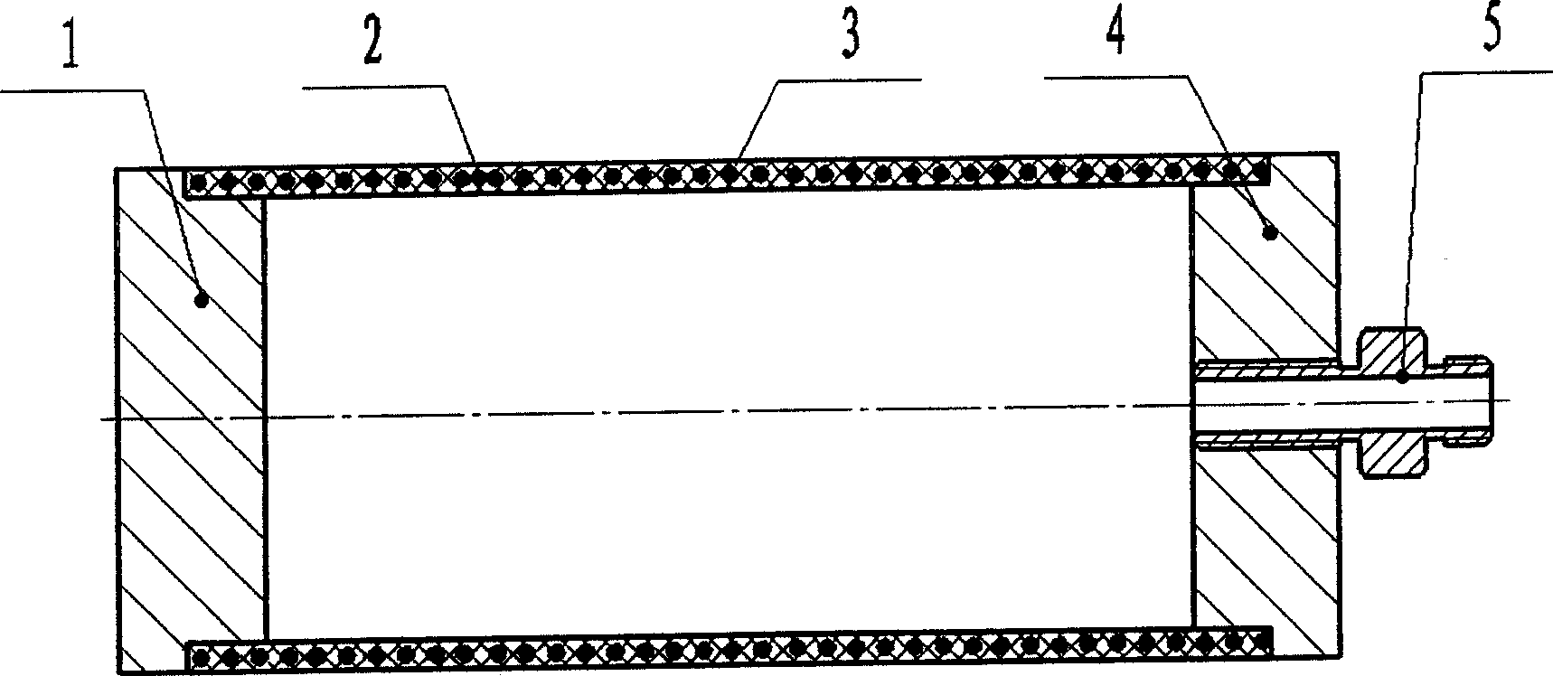
[0009] refer to figure 1 , a pneumatic flexible driver, including a left end cover 1, a rubber tube 2, a spring 3 nested in the wall of the rubber tube, a right end cover 4, and a pipe joint 5, the two ends of the rubber tube 2 are respectively connected to the left end The cover 1 and the right end cover 4 are sealed and connected by superglue, and can also be sealed and connected in other ways. There is a threaded hole in the middle part of the right end cap 4, and the pipe joint 5 is installed on the right end cap 4 through threads, so that the inner cavity of the rubber tube 2 communicates with the atmosphere through the pipe joint 5.

[0010] The working principle of the present invention is: the compressed gas is filled into the inner cavity of the rubber tube 2 through the pipe joint 5 and the right end cover 4, and under the ...


PUM


Abstract

This invention relates to an air flexible impeller, comprising end caps and rubber pipe with its two end sealed connected to the two end caps via strong glued joint, wherein, one of the end caps is equipped with pipe joint, the pipe wall is nested with a spring to enhance the impeller's elasticity and rigidity. The impeller has simple structure, and convenient assemblage and good hermeticity.

Description

(1) Technical field [0001] The invention relates to a driver, in particular to a pneumatically flexible driver suitable for driving a robot finger. (2) Background technology [0002] Efficient and flexible drives are the basis and prerequisite for the design of robotic multi-fingered dexterous hands. Traditional robotic multi-fingered dexterous hands mostly use motors as drives, and their structural size is large, making it difficult to miniaturize multi-fingered dexterous hands. There is also proposed flexible cylinder, which can be used for driver and joint design, as the publication number is CN87107075A, and the patent name is the Chinese invention patent of pneumatic flexible cylinder and bending and torsion joints, which discloses a pneumatic flexible cylinder, which consists of end cap, ferrule, screw Composed of steel wire and rubber wall, the ferrule is connected to the end cover by screws, and the rubber wall is clamped in the cone surface formed by the end cap hea...

Claims


Application Information

Patent Timeline
Patent Type & Authority Applications(China)
IPC IPC(8): B25J13/00
Inventor 张立彬杨庆华鲍官军阮健
Owner ZHEJIANG UNIV OF TECH
Learn More