Scattered-light alarm

A technology of scattered light and smoke alarms, applied in the direction of alarms, fire alarms, scattering characteristics measurement, etc., can solve problems such as negative effects of sensitivity

Inactive Publication Date: 2010-05-12
SIEMENS SWITZERLAND
View PDF10 Cites 0 Cited by
  • Summary
  • Abstract
  • Description
  • Claims
  • Application Information

AI Technical Summary

Problems solved by technology

In addition to the aging of the optoelectronic components, especially if the optical surfaces of the components through which the light passes are soiled, this has a negative effect on the sensitivity

Method used


Image

  • Scattered-light alarm
  • Scattered-light alarm
  • Scattered-light alarm

Examples


Embodiment Construction

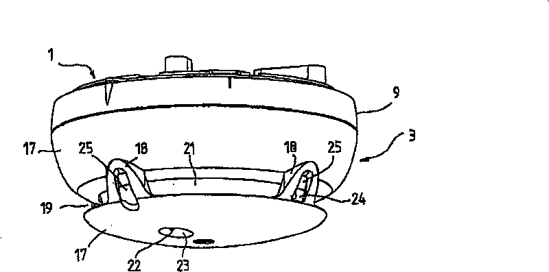
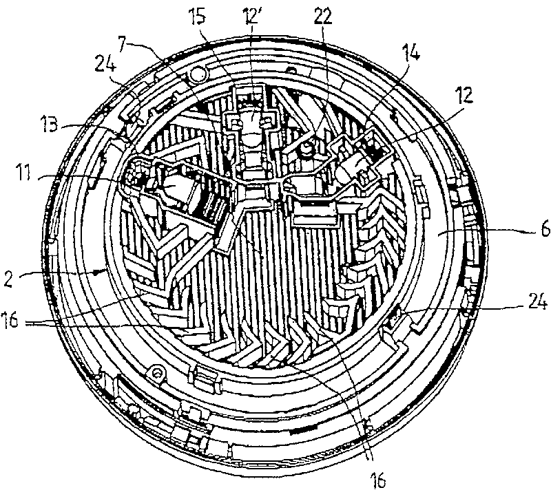
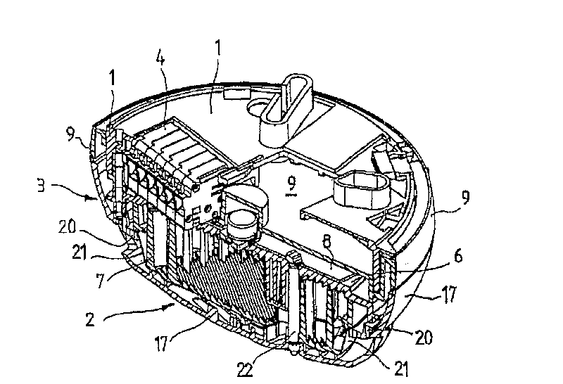
[0019] Figure 1-4 The illustrated smoke alarm comprises three known main components, namely a base 1 , an optical sensing device 2 and a housing 3 . Its structure can in particular be derived from image 3 seen in. figure 2 A cross-sectional view through part of the optical sensing device 2 of the smoke alarm is shown from below.

[0020] The base 1 is mounted to the ceiling of the surveillance space, either directly to a wall outlet or to a surface with or without a base. The base 1 mainly comprising a circular plate and a skirt protruding downward also comprises a socket 4 ( image 3 , 4), it is used to undertake the contact piece 5 ( Figure 4 ).

[0021] The optical sensing device 2 includes a sheet-like support 6 for the optical sensor, a cap-shaped labyrinth spacer 7 fixed on the underside of the support 6 , an electroanalytical element arranged on the upper side of the support 6 facing the base 1 The printed circuit board 8 , the cover 9 that seals the printed c...


PUM


Abstract

The smoke detector comprises an optical measuring chamber, comprising a sensor arrangement (2) with at least one light source (12, 12'), a light sensor (11) and a labyrinth system (7) with diaphragms(16) arranged at the periphery of the measuring chamber. The light sources (12, 12') and the light sensor (11) are each arranged in a housing (14, 15; 13). Said housings (14, 15; 13) have a rectangular form and comprise a small window opening. The at least one light source (12, 12') and the light sensor (11) are arranged in the rear section of the housing (14, 15; 13) and a relatively large separation is formed between the optical surfaces of the at least one light source (12, 12') through which light passes and / or the lens of the light sensor (11). Said separation is preferably greater than the diameter of said optical surfaces or said lens. A compact, open dispersion chamber is formed in the measuring chamber between the light exit or entry of the housing (14, 15; 13) and the opposing diaphragm (16).

Description

technical field [0001] The invention relates to a scattered light smoke alarm comprising an optical measuring chamber comprising a sensing device having at least one light source and one light receiver and a labyrinth-type isolation assembly of spacers arranged on the circumference of the measuring chamber, wherein the The at least one light source and light receiver are respectively arranged in the casing. Background technique [0002] In scattered light smoke detectors, which optionally include other sensors, such as temperature sensors, in addition to the optical measuring chamber, known optical measuring chambers are designed in such a way that interfering extraneous light does not penetrate into them, but smoke easily enters into them. The at least one light source and its light receiver are arranged such that the light beam does not take a direct path from the at least one light source to its light receiver. In the presence of smoke in the light beam, light from at le...

Claims


Application Information

Patent Timeline
Patent Type & Authority Patents(China)
IPC IPC(8): G08B17/107G01N21/53
CPCG08B17/107G08B17/113
Inventor K·赫斯U·里迪
Owner SIEMENS SWITZERLAND
Why Eureka
Try Eureka