
Electromagnetic rotary piston pump and multistage electromagnetic rotary piston pump

A piston pump and electromagnetic technology, applied in the field of electromagnetic rotary piston pump, can solve problems such as pressure discontinuity, and achieve the effects of reducing kinetic energy loss, reducing operating costs, and increasing gas flow

Inactive Publication Date: 2005-08-17
DELTA ELECTRONICS INC
View PDF0 Cites 9 Cited by
  • Summary
  • Abstract
  • Description
  • Claims
  • Application Information

AI Technical Summary

Problems solved by technology

[0006] The present invention proposes an electromagnetic rotary piston pump, the main purpose of which is to obtain continuous gas pressure to solve the problem of discontinuous pressure in known electromagnetic reciprocating piston pumps

Method used


Image

  • Electromagnetic rotary piston pump and multistage electromagnetic rotary piston pump
  • Electromagnetic rotary piston pump and multistage electromagnetic rotary piston pump
  • Electromagnetic rotary piston pump and multistage electromagnetic rotary piston pump

Examples


Embodiment Construction

[0023] The electromagnetic rotary piston pump proposed by the present invention uses the electromagnetic force of an external electromagnetic coil to accelerate the piston in an annular (doughnut-shaped) tube with a through hole and rotate continuously to compress the gas.

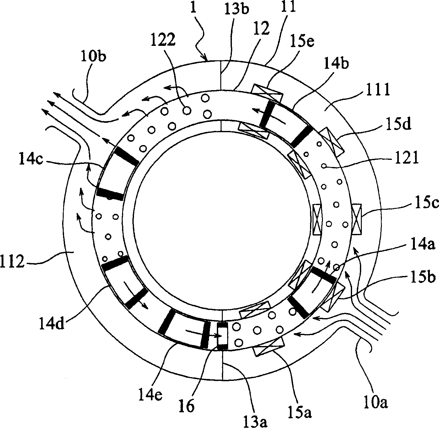
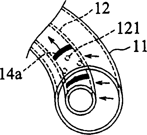
[0024] See Figure 2A and Figure 2B , in the first embodiment, the electromagnetic rotary piston pump 1 of the present invention comprises an outer annular pipe 11 of a plastic material, an inner annular pipe 12 of a brass material, two annular partition plates 13a and 13b, and five pistons 14a to 14e and five sets of electromagnetic coils 15a to 15e.

[0025] In detail, the inner annular pipe 12 is wrapped by the outer annular pipe 11, and a plurality of through holes 121 and 122 are distributed on the wall surface, and two annular partition plates 13a and 13b are placed inside the outer annular pipe 11. The outside of the annular pipe 12 divides the interior of the outer annular pipe 11 into two airti...


PUM


Abstract

This invention relates to electromagnetic revolutionary piston pump, which comprises one doughnut tube, one outer tube; two ring separation plate, several pistons and one electromagnetic coil. The doughnut tube wall is distributed with multiple through holes and multiple second through holes with the above pistons. The outer tube has one intake opening and one exhaust opening to cover the doughnut tube. Besides, the two ring separation plate is put into the outer ring tube to separate the outer tube into one first airproof space connected with first through holes and one second airproof space connected with second through holes.

Description

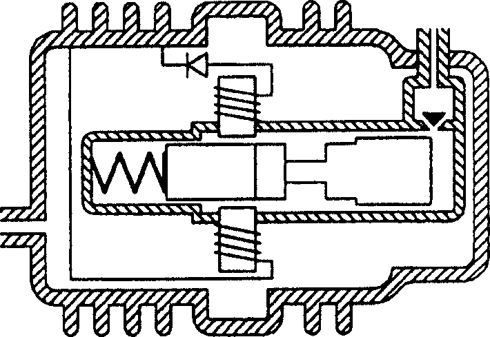
technical field [0001] The invention relates to a piston pump, in particular to an electromagnetic rotary piston pump. Background technique [0002] Pneumatic pump is a device that uses mechanical principles to reduce gas volume and increase gas pressure. Generally, there are three types: reciprocating, centrifugal and axial flow. Among them, reciprocating pumps are most commonly used by people because they can obtain a wider pressure range. . [0003] The reciprocating pump mainly uses a piston to reciprocate in a certain space to compress the gas to generate pressure, so it is also called a reciprocating piston pump. At present, in order to allow the reciprocating piston pump to obtain greater gas pressure, it is usually to use electromagnetic force to drive the piston, such as figure 1 shown. [0004] However, figure 1 The illustrated reciprocating piston pump has the following problems. First, since the piston has to return to the initial position to perform the nex...

Claims


Application Information

Patent Timeline
Patent Type & Authority Applications(China)
IPC IPC(8): F04B35/04F04B41/06
Inventor 沈德洋游原盈陈李龙叶鸣
Owner DELTA ELECTRONICS INC
Learn More