
Stayed cable shock attenuation device

A vibration damping device and cable-stayed technology, which is applied in the direction of cable-stayed bridges, bridge parts, bridge forms, etc., can solve the difficulty of manufacturing and installing damping devices, the increase in the manufacturing cost of shock absorber connecting components, and the landscape of cable-stayed bridges. Impact and other issues, to achieve the effect of reducing cost, improving quality, and improving vibration reduction effect

Active Publication Date: 2005-08-10
CHINA RAILWAY BRIDGE SCI RES INST LTD
View PDF3 Cites 32 Cited by
  • Summary
  • Abstract
  • Description
  • Claims
  • Application Information

AI Technical Summary

Problems solved by technology

In order not to affect the beauty of the bridge, the designer usually requires that the installation height of the shock absorber should not exceed the height of the bridge railing (about 1.5 meters), and for a cable-stayed bridge with a large span, in order to achieve a satisfactory damping effect, the shock absorber The height of the bridge deck will reach 2-3 meters, sometimes higher, and the higher the installation position of the shock absorber, in order to ensure the rigidity of the connection and not to lose stability (because the connecting member is sometimes under tension and sometimes under compression), the connection The size of the component will be larger, which not only increases the manufacturing cost of the shock absorber connection component, but also has a very adverse impact on the landscape of the cable-stayed bridge
In addition, since the inclination angles of the stay cables at different positions of the cable-stayed bridge are different, in order to ensure the damping effect of the damper, the damper should be perpendicular to the stay cables, so that the angles between the connecting members and the bridge deck at different positions are also different. Therefore, the design, manufacture and installation of the damping device of the existing cable-stayed damping device are relatively difficult.

Method used


Image

  • Stayed cable shock attenuation device
  • Stayed cable shock attenuation device

Examples


Embodiment Construction

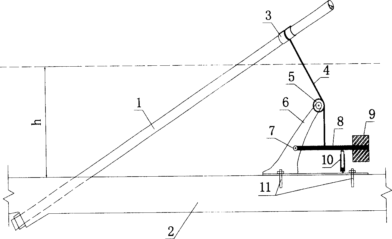
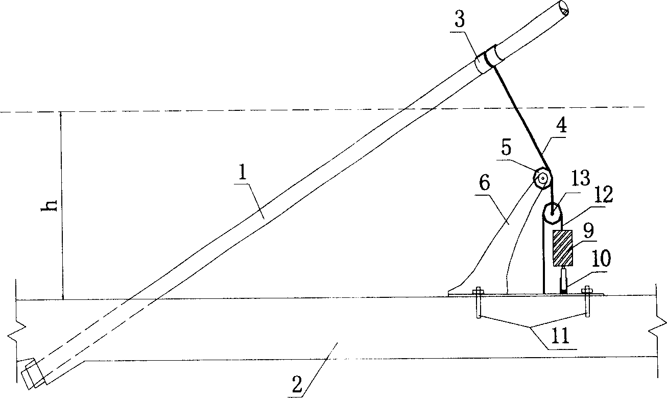
[0030] exist figure 1 Among them, one end of the connecting cable 4 is connected to the cable clip 3 connected to the stay cable 1, and the other end is connected to the lever 8 with a weight 9. The middle of the connecting cable 4 is connected with a fixed pulley 5 installed on the support 6. Turn, so that the two ends of the connecting cable 4 are perpendicular to the top surfaces of the stay cables 1 and the main beam 2 respectively. The lever 8 is connected to the support 6 via the pin 7 . A damper 10 is installed between the lever 8 and the main beam 2. The damper 10 can be a passive damper such as an oil damper or a viscous shear damper to realize the passive control of the vibration of the cable stay, or a magnetic current Semi-active dampers such as variable dampers and variable friction dampers can realize semi-active control of cable vibration, and even active dampers such as piezoelectric dampers and magnetostrictive dampers can be used to realize active control of...


PUM


Abstract

The present invention relates to an inclined stay cable vibration damping equipment. It is characterized by that it is an inclined stay cable vibration damping system consisting of connecting cable, weight, lever, damper and support abutment. Said system uses the suspended weight to provide tension for connecting cable, and utilizes the connecting cable to transfer the damping force provided by damper connected with bridge surface, elastic force and mass force of suspended weight to change the modal mass, damping value and rigidity so as to attain the goal of damping vibration.

Description

technical field [0001] The invention belongs to the technical field of vibration reduction of cable stays. Background technique [0002] The cable-stayed cables of long-span cable-stayed bridges are the main load-bearing components of cable-stayed bridges. With the continuous increase of the span of cable-stayed bridges, the cable-stayed cables become longer and longer. Because the cable-stayed cables are long and soft, their resistance The bending stiffness is small and the natural vibration frequency is low. Generally, the first three order natural vibration frequencies are all below 2Hz, and the modal damping ratio is extremely small, generally only about 0.001 (the logarithmic attenuation rate is below 0.007). Excessive vibration occurs under external excitations such as wind-rain, earthquake and traffic, and even large-scale divergent vibration occurs. The vibration of the stay cable will make it under the action of a large alternating stress cycle for a long time. In ...

Claims


Application Information

Patent Timeline
IPC IPC(8): E01D11/04E01D19/16
Inventor 汪正兴任文敏
Owner CHINA RAILWAY BRIDGE SCI RES INST LTD
Learn More