Surface mounted sensor

A surface mount, inductor technology, applied in the direction of inductors, fixed inductors, transformer/inductor coils/windings/connections, etc., can solve the problems of insulation coating damage, etc., and achieve the effect of high anti-drop impact performance

Inactive Publication Date: 2005-05-25
TOKO KABUSHIKI KAISHA
View PDF2 Cites 23 Cited by
  • Summary
  • Abstract
  • Description
  • Claims
  • Application Information

AI Technical Summary

Problems solved by technology

[0008] In such a structure, in order to connect both ends 23a, 23b of the air-core coil 23 to the terminal electrode 24, the flat wire must be bent (bending portion 25) at the winding start, winding end portion, and joining portion 24a. As a result, the insulating coating of the bent part of the flat wire is damaged, and there are reliability problems such as heat generation and short circuit when a large current flows.

Method used


Image

  • Surface mounted sensor
  • Surface mounted sensor
  • Surface mounted sensor

Examples


Embodiment Construction

[0018] Refer below figure 1 and 2 An embodiment of the present invention is described.

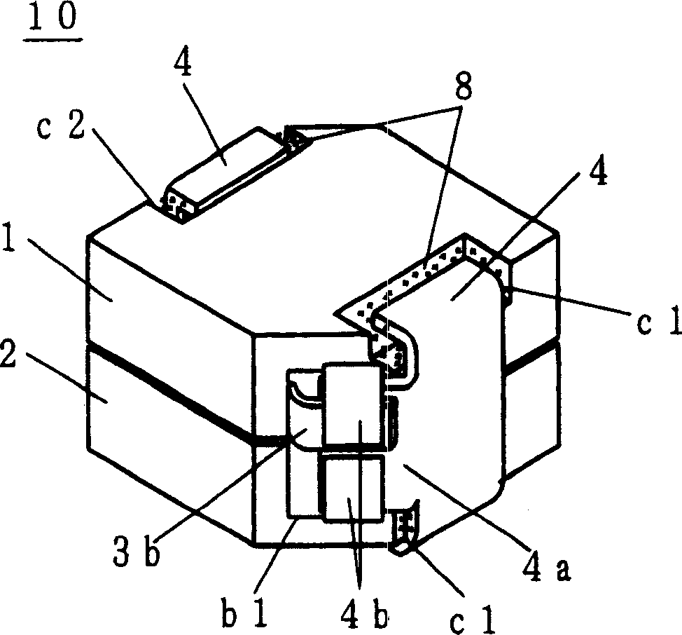
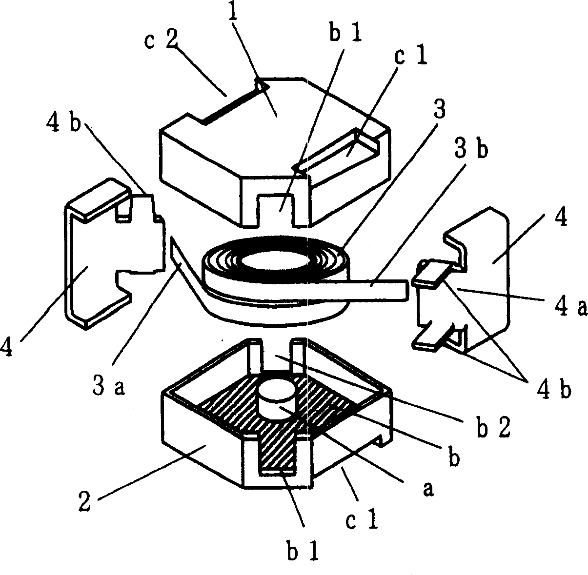
[0019] figure 1 It is a perspective view of a surface mount sensor according to an embodiment of the present invention. figure 2 yes figure 1 An exploded perspective view of the surface mount sensor shown. Such as figure 1 and figure 2 As shown, in the surface-mounted inductor 10 of the present invention, 1 and 2 represent pot-shaped magnetic cores with dimples, 3 represents an air-core coil, and 4 represents the structure of connecting terminals.

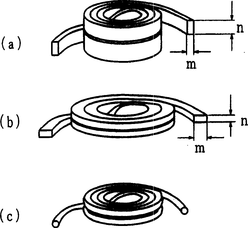
[0020] The air-core coil 3 uses an insulated coated wire with a thermal adhesive layer on the surface and a wide quadrilateral cross section, that is, a flat wire. The initial end and terminal end 3a, 3b of the two-layer winding are drawn out to the outer circumference, that is, the α winding .

[0021] The dimpled pot cores 1 and 2 are formed by molding and sintering ferrite magnetic materials into a roughly square shape, and are equ...


PUM


Abstract

It is an object of the present invention to provide a surface mount type inductor in which a winding end can be joined to a connection electrode without bending, and the reliability of fixing the magnetic core can be improved. In a surface mount type inductor that accommodates two dimpled pot cores and an air core coil inside, the dimpled pot core has a core as a winding core inside, and the upper A pair of opposite end faces are provided with terminal engagement recesses, and a pair of opposite cutouts are provided at lower ends of the side faces. The air-core coil is wound by an insulated coated wire with a thermal adhesive layer on the surface. The winding initial end and the winding end end of the winding are drawn out to the outer circumference of the winding, which is a so-called α-coil coil. A connection terminal having a U-shaped cross-section and a terminal engaging recess that is configured to sandwich two pot-shaped magnetic cores with dimples combined together, and further has a terminal extending from the center of one end of the connection terminal. the connection part.

Description

technical field [0001] The present invention relates to components for electronic instruments, in particular to a surface mount type (SMD) inductor. Background technique [0002] In recent years, along with the increase of portable electronic equipment such as mobile communication equipment, it is required to reduce losses and improve efficiency of electronic parts and circuits. Especially for coils for switching power supplies, many attempts have been made to reduce as much as possible the high-frequency loss caused by the increase in frequency accompanying miniaturization and the resistance heating caused by the current. [0003] As an example, in Japanese Patent Laid-Open No. 1995-288210, it is introduced that in order to improve the space factor of the winding wire, a flat wire is used to be wound into a spiral shape, and the DC resistance Rdc of the winding wire is reduced as much as possible so that the current caused by SMD choke coils for switching power supplies wi...

Claims


Application Information

Patent Timeline
IPC IPC(8): H01F27/28H01F17/04H01F27/29H01F37/00
Inventor 佐佐森邦夫小久保贵司兵头功一郎
Owner TOKO KABUSHIKI KAISHA
Why Eureka
Try Eureka