
Device for conveying printing material in a machine

A technology for conveying systems and printing materials, applied in the field of conveying systems, can solve problems such as low adjustment dynamic performance, and achieve the effects of high transfer dynamic performance, fast path change, and precise mechanical guidance

Inactive Publication Date: 2005-05-11
HEIDELBERGER DRUCKMASCHINEN AG
View PDF4 Cites 0 Cited by
  • Summary
  • Abstract
  • Description
  • Claims
  • Application Information

AI Technical Summary

Problems solved by technology

However, high adjustment forces and wide adjustment strokes are required for this, which leads to low adjustment dynamics

Method used


Image

  • Device for conveying printing material in a machine
  • Device for conveying printing material in a machine
  • Device for conveying printing material in a machine

Examples


Embodiment Construction

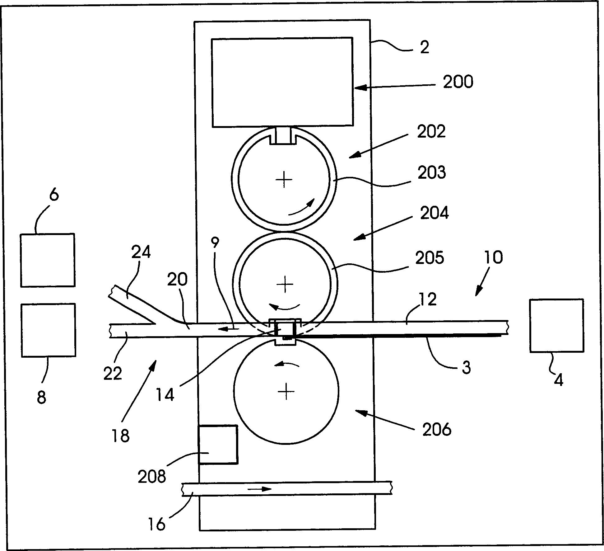
[0074] figure 1 A schematic side view of a printing unit 2 of a printing press 1 that processes printing materials 3 , for example in the form of printed sheets, is shown. At least one unit 4 is provided in front of the printing unit 2, such as an additional printing unit or a sheet feeder, and at least two units 6, 8 are provided behind the printing unit, such as additional printing units, Coating units, dryers, sheet receivers or finishing units (such as cutters, folders, punchers, binders or packaging stations).

[0075] The printing unit has an inking and / or dampening unit 200 with rollers, a printing plate cylinder with a tensioned printing plate 203 (for example a printing plate or a printing sleeve), a tensioned transfer cloth 205 (such as a blanket or blanket cover) transfer roller 204 and a counterpress roller 206. Furthermore, the printing unit 2 can also have a separate electric motor 208 for driving the cylinders and rollers, or the printing unit can be driven by...


PUM


Abstract

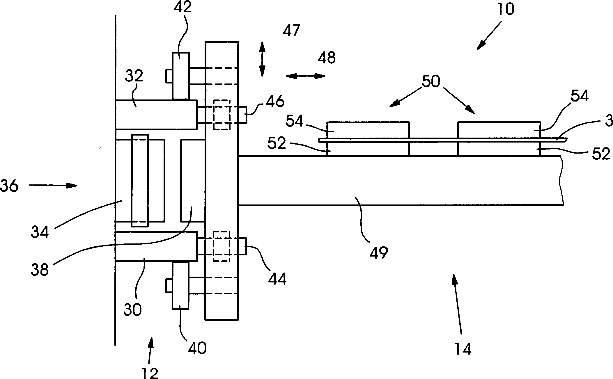
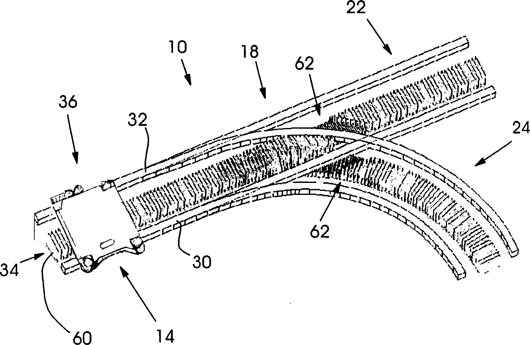
The conveyor system according to the invention for use in a printing material handling machine has a guide with at least one switch, the conveyor system also has at least one mover movable along the guide and an electric linear drive , the electrical linear drive has a primary part comprising a winding core and a secondary part comprising a mover, characterized in that, in the area of ​​the switch, in order to form a recess for at least one guide section of the guide At least one winding core has a height that is smaller than the height of the winding cores outside the region of the switch.

Description

technical field [0001] The invention relates to a conveying system in a printing material processing machine. [0002] Furthermore, the invention relates to a method for producing a primary part of an electrical linear drive. Background technique [0003] It is known that in printing material processing machines, such as printing presses, the printing material to be processed, such as a printing material sheet (hereinafter referred to as sheet), is transported by means of a transport system based on an electrical linear drive. [0004] It is also known that in printing material processing machines, such as cylinder printing machines, the web of printing material to be processed (hereinafter referred to as: belt) is drawn into the machine prior to the actual printing process by means of a transport system based on an electric linear drive middle. [0005] It is also known to provide transfer systems with switchable switches for branching and / or merging and for this purpose....

Claims


Application Information

Patent Timeline
Patent Type & Authority Applications(China)
IPC IPC(8): B65H5/00B41F13/004H02K41/02H02K41/03
CPCH02K41/03B41F13/0045B41P2213/128H02K3/18
Inventor 亨德里克·弗兰克弗兰克·巴尔安提迪特马尔·贝格尔托马斯·舍费尔伊沃内·施勒魏斯
Owner HEIDELBERGER DRUCKMASCHINEN AG
Learn More