Electronic ballast method and apparatus for gas discharge lamp

A gas discharge lamp and electronic ballast technology, applied in the field of electronics, can solve the problems of short life of electronic ballast, electromagnetic interference, power consumption, etc., achieve clear circuit operation, prevent acoustic resonance phenomenon, and prolong lamp life. Effect

Inactive Publication Date: 2005-04-27
祁辉
View PDF0 Cites 1 Cited by
  • Summary
  • Abstract
  • Description
  • Claims
  • Application Information

AI Technical Summary

Problems solved by technology

But the trigger is a vulnerable part, and the reason why many lights are not on is because the trigger is not working properly.
Another disadvantage of inductive ballasts is low power factor and power consumption, which also makes wiring and distribution transformers many times larger than incandescent lamps of the same power, resulting in a serious waste of resources.
[0003] Existing HID electronic ballasts have defects such as saving electricity but not saving money, short life, serious electromagnetic interference, etc., so far they have not been popularized
The reason is that the current HID lamp electronic ballast uses a half-bridge or a full-bridge to output directly through the inductor. Due to the special working mode of the HID lamp, the large current required for the initial start-up is directly provided by the AC / DC conversion (DC / AC for short) circuit. The power tube in the tube is obtained, so the loss of the power tube is large and the heat is serious, which is one of the causes of the short life of the electronic ballast.

Method used


Image

  • Electronic ballast method and apparatus for gas discharge lamp
  • Electronic ballast method and apparatus for gas discharge lamp
  • Electronic ballast method and apparatus for gas discharge lamp

Examples


Embodiment Construction

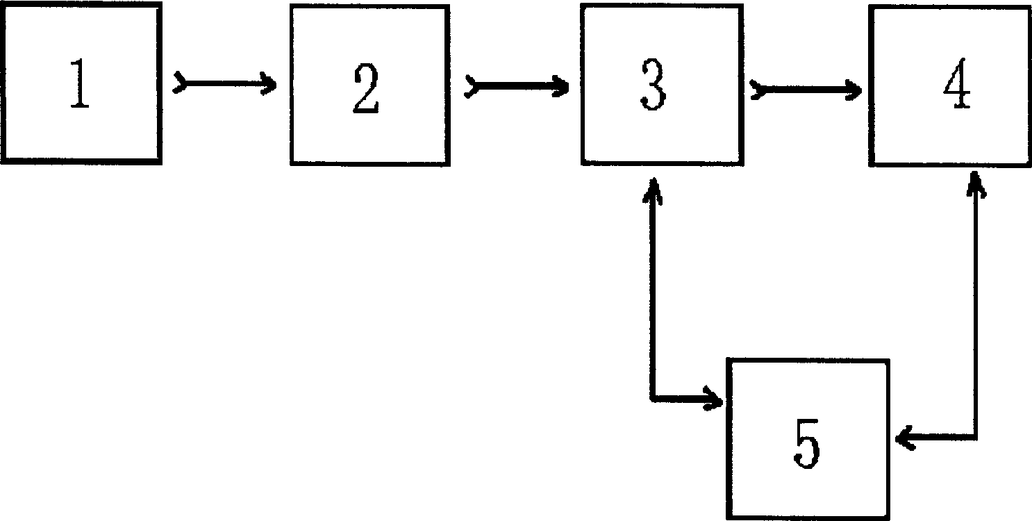
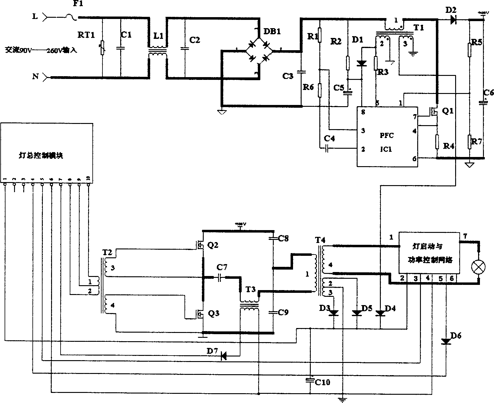
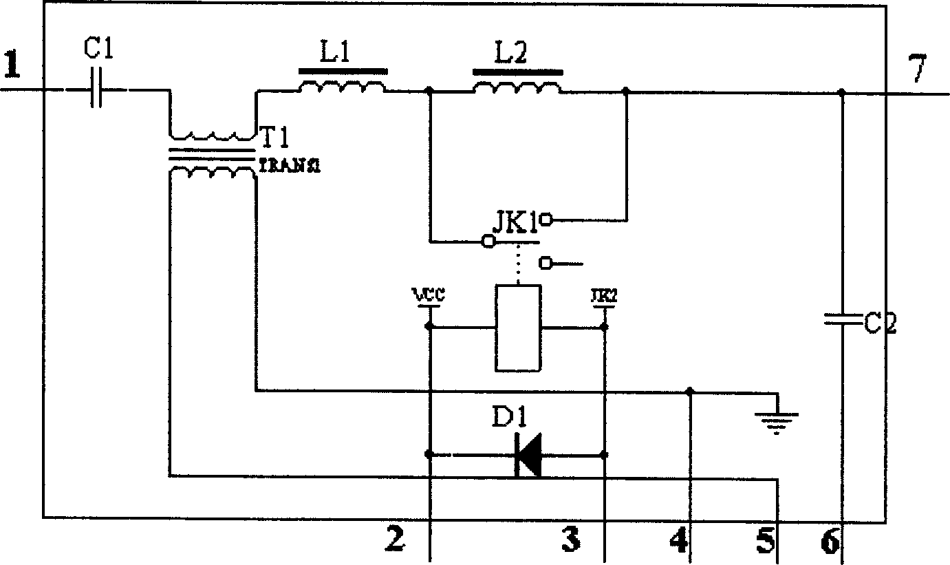
[0022] see Figure 1 ~ Figure 4 .

[0023] The rectification circuit is composed of fuses F1, RT1, C1, L1, C2, DB1, C3 and other components. The fuse is connected in series to the main circuit to protect the entire circuit from overload current. RT1 is a piezoresistor, which limits the high input voltage. C1, common mode inductance coil L1 and C2 form an EMI filter circuit so that external signals cannot enter the main circuit, and internal interference cannot be radiated outward. DB1 and C3 constitute an AC-to-DC rectifier filter circuit.

[0024] The power factor correction (PFC) circuit doubles as a voltage boost, and there are basically two types of power factor correction. One is a passive PFC circuit and the other is an active PFC circuit. In particular, the active PFC circuit can achieve low harmonics and high power factor (PF 0.98 or more), which means that the input current waveform of the electrical appliance is close to a sine wave and has the same phase as the...


PUM


Abstract

The present invention discloses electronic ballasting method and device for gas discharge lamp. The electronic ballasting device includes EMC filter and rectifier circuit to provide power source, power factor correcting and voltage raising circuit to generate high DC voltage, high frequency DC/AC converter to form high frequency AC voltage, total control circuit, and lamp initiating and power control network to power the lamp tube of gas discharge lamp. The present invention has small electromagnetic radiation, less harmonic wave, high power factor, low temperature raise, obvious power saving effect, long life and other features.

Description

technical field [0001] The invention relates to the field of electronics, in particular to an electronic ballast method and device for a high-intensity gas discharge lamp. Background technique [0002] Among various light sources, high-intensity discharge lamps (HID for short) exhibit high luminous efficacy and excellent light color reproduction. HID lamps have been used for high-intensity lighting of many large areas. Such as roads, stages and other large occasions. But the use of these HIDs must be equipped with a dedicated ballast device. Among them, inductive ballasts are widely used, but this kind of ballast has great defects, and the use of this inductive ballast must be equipped with a trigger. But the trigger is a vulnerable part, and the reason why many lights are not on is because the trigger is not working properly. Another disadvantage of magnetic ballasts is low power factor and power consumption, which also makes wiring and distribution transformers many ti...

Claims


Application Information

Patent Timeline
Patent Type & Authority Applications(China)
IPC IPC(8): H05B41/14H05B41/288
Inventor 祁辉
Owner 祁辉
Why Eureka
Try Eureka