Heat pulse time difference type flow detection method

A technology of flow detection and thermal pulse, which is applied in mass flow measurement devices, indirect mass flow meters, etc., can solve the problems of high energy consumption and sensor loss, increase the measurement range, and move the saturation point of the curve backward, so as to reduce loss, Energy Saving Effect

Inactive Publication Date: 2005-04-06
ZHEJIANG UNIV
View PDF0 Cites 14 Cited by
  • Summary
  • Abstract
  • Description
  • Claims
  • Application Information

AI Technical Summary

Problems solved by technology

Although the linearity of the upstream and downstream temperature difference curve thus obtained is affected in the low-speed section, the saturation point of the curve has to be moved later, thereby increasing the measurement range
[0005] The common problem of the above two measurement methods is that if they are used in occasions that require real-time monitoring of the flow rate, both measurement methods need to supply power to the heating element for a long time to keep it in a heating state, so the energy consumption and the sensor itself Loss is bigger

Method used


Image

  • Heat pulse time difference type flow detection method
  • Heat pulse time difference type flow detection method
  • Heat pulse time difference type flow detection method

Examples


Embodiment Construction

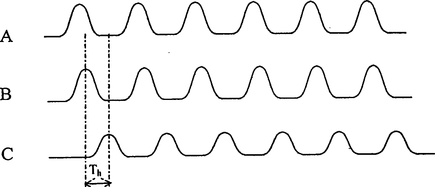
[0022] 1. Thermal pulse time-difference flow detection method, such as figure 1 Shown:

[0023] 1) Put the sensor into the pipeline parallel to the direction of flow velocity, and use the pulse power supply to provide pulse power supply to the heating temperature measuring element or heating element, and the heating signal is the heating pulse input signal A; generated in the heating temperature measuring element or heating element The pulse current is measured, and the temperature change of the heating temperature measuring element or the temperature measuring element representing the temperature of the heating element is measured to obtain a pulse curve, that is, the output signal curve B of the heating temperature measuring element or the temperature measuring element representing the temperature of the heating element;

[0024] 2) Measure the temperature change of the temperature measuring element downstream of the heating temperature measuring element or the temperature m...


PUM


Abstract

This invention discloses a heat impulse time lag flow measurement method, which puts sensor in the parallel pipe to the flow direction to get heating temperature measurement, or its denote output signal curve; then it measures the temperature change on downstream of temperature measurement element along flow direction to get output signal curve of temperature element; it compares two curves to measure the time lag value to get flow speed. This invention especially applied in the measurement of middle and low speed range of gas with constant components.

Description

technical field [0001] The invention relates to a mass flow detection method, in particular to a thermal pulse time difference flow detection method. Background technique [0002] Existing thermal flowmeters are divided into two types, 1. Anemometer; 2. Thermal flow sensor. [0003] Anemometers work based on the Golden Law introduced in 1914 to detect flow velocity by detecting the degree of heat dissipation from the heater itself when exposed to the fluid. The sensor of this mode includes a straight channel with fixed geometric dimensions, a heater made of temperature-sensitive material, a reference temperature sensor for measuring the original temperature of the fluid and the corresponding control and measurement circuit. How much heat is used to measure the flow rate. The sensor element can be made of various temperature-sensitive materials. This sensor has a high response frequency and a large speed measurement range, but it cannot be used for long-term measurement, c...

Claims


Application Information

Patent Timeline
Patent Type & Authority Applications(China)
IPC IPC(8): G01F1/86
Inventor 傅新谢海波段萱苡杨华勇
Owner ZHEJIANG UNIV
Why Eureka
Try Eureka