
Liquid crystal display device

A liquid crystal display device, backlight device technology, applied in static indicators, optics, instruments, etc., can solve the problems of unpleasant sound, unpleasant sound, etc., achieve the elimination of unpleasant sound, simple device cost, and prevent the generation of friction sound Effect

Inactive Publication Date: 2005-03-30
SONY GRP CORP
View PDF1 Cites 14 Cited by
  • Summary
  • Abstract
  • Description
  • Claims
  • Application Information

AI Technical Summary

Problems solved by technology

Therefore, especially after the liquid crystal display device is started, there is heat generated by lighting the light source of the backlight device, and the members rub against each other due to the difference in expansion of the frame and various members, and an accompanying unpleasant sound is generated. The problem
Moreover, not only after starting, but also after stopping, there is a possibility that the components rub against each other due to the difference in the contraction of the frame or various components, and in a short time, an accompanying unpleasant sound is emitted from the liquid crystal display device. question

Method used


Image

  • Liquid crystal display device
  • Liquid crystal display device
  • Liquid crystal display device

Examples


Embodiment 1

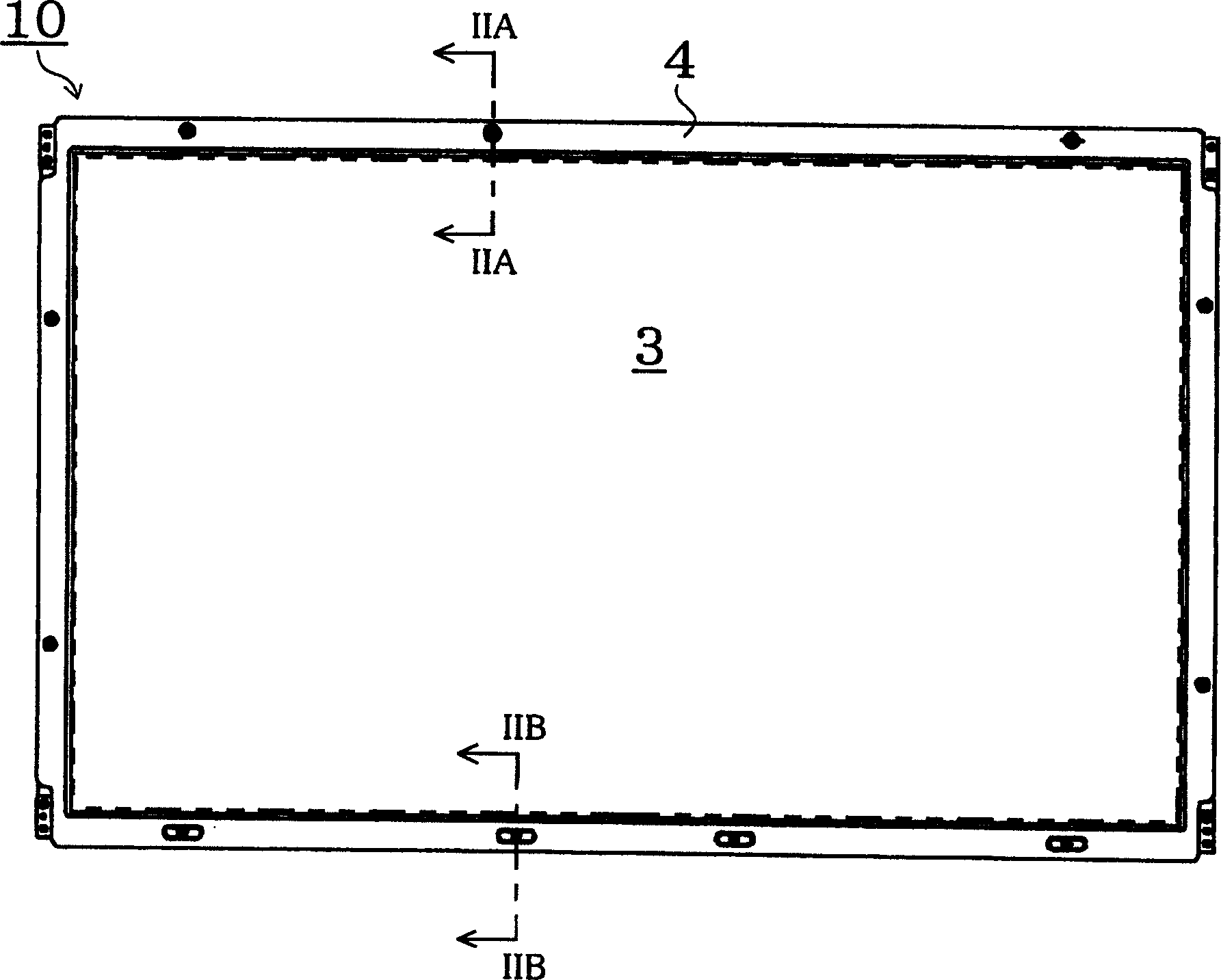
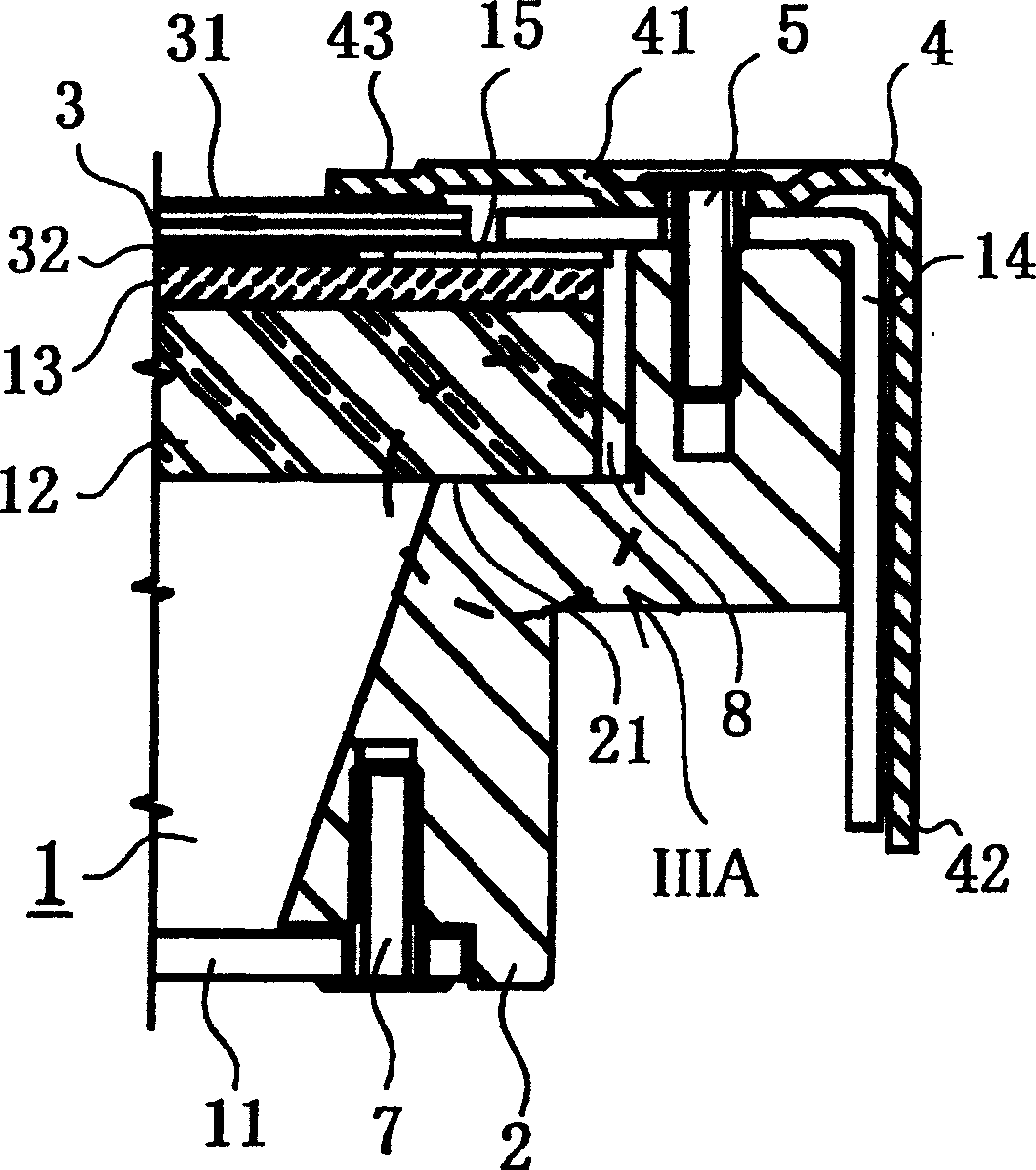
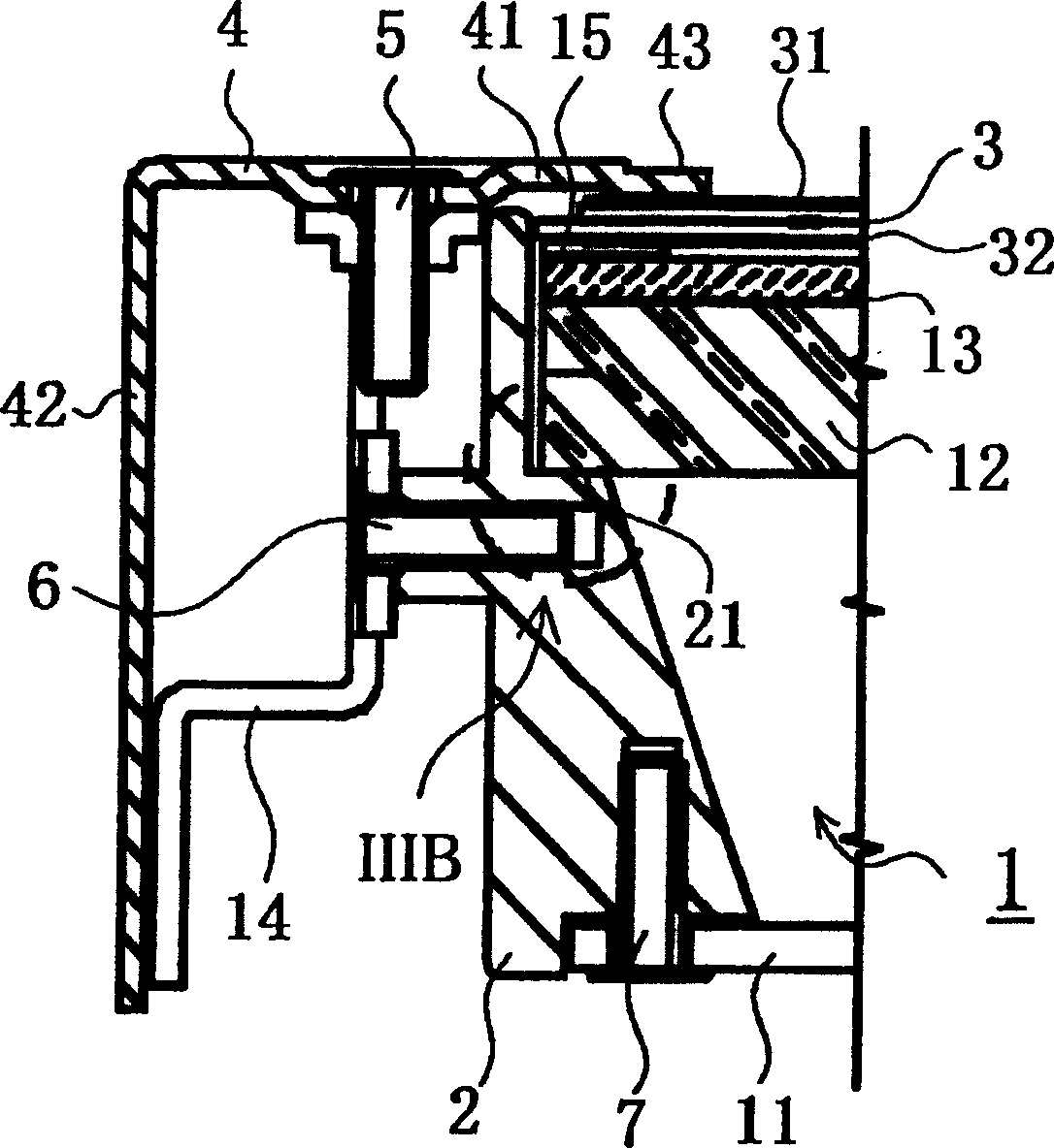
[0043] figure 1 It is a plan view of the liquid crystal display device according to Embodiment 1 of the present invention. Figure 2A Yes figure 1 IIA-IIA enlarged cross-sectional view of the liquid crystal display device, Figure 2B Yes figure 1 IIB-IIB enlarged cross-sectional view of the liquid crystal display device. in addition, Figure 3A Yes Figure 2A Enlarged view of part IIIA, Figure 3B Yes Figure 2B Enlarged view of part IIIB. Figure 4 is a perspective view showing another example of the friction reducing device in Embodiment 1, Figure 5 It is a perspective view showing still another example of the friction reducing device in the first embodiment.

[0044] figure 1 The liquid crystal display device 10 of the embodiment 1 shown in FIG. It is supported between the frame-shaped bezel cover 4 and the support portion 21 provided on the frame 2 of the backlight unit 1 . For convenience of description, below, the display surface of the liquid crystal di...

Embodiment 2

[0061] In the case of a large-sized liquid crystal display device, the central portions of the back reflection plate 11, the reinforcing plate 12, and the diffusion plate 13 tend to bend due to their own weight. Thus, there are cases where, on the central portion of the backlight unit 1, etc., for example, conical protrusions called spacer pins are provided to support optical plates such as the reinforcement plate 12 or the diffusion plate 13, Also, a reinforcement member is provided on the back reflection plate 11 . The method of providing this spacer pin is very effective for stable display in a large liquid crystal display device. In addition, the method of providing a reinforcing member on the back reflector can use a thin metal plate as the back reflector 11, so It is very effective for weight reduction and strength maintenance of a large liquid crystal display device.

[0062] However, if such spacer pins or reinforcing members are used, the contact surfaces of the spac...


PUM


Abstract

In a liquid crystal display device provided with a backlight unit, creak reduction means is provided at least on one part of the areas where members constituting the liquid crystal display device such as the liquid crystal panel, the diffusion plate, the reinforcing plate, the frame of the liquid crystal display device and the back surface reflector for the backlight unit come into contact with each other. The creak reduction means may be a slippery film whose surface is fluorinated such as a fluororesin film, a polyacetal resin film, a polyethylene film, and a silicon coating film, or protrusions or protruding fins, or a friction reduction means such as silicon oil or fluorine oil, or a mutual displacement absorbing means such as a flexible sheet. By adopting such a constitution, it is possible to prevent noise from being generated due to mutual friction between the liquid crystal panel and the various members such as the diffusion plate, the reinforcing plate, the frame and the reflector for the backlight unit as a result of thermal expansion.

Description

technical field [0001] The present invention relates to sound countermeasures in large-scale liquid crystal display devices, and in particular, relates to preventing thermal expansion of various components of liquid crystal display devices such as the liquid crystal panel, the diffuser plate and the reinforcement plate of the backlight unit, and the frame after the liquid crystal display device is started. The liquid crystal display device that produces unpleasant sounds caused by mutual friction. Background technique [0002] Recently, in liquid crystal display devices, strive to increase in size, generally is a liquid crystal display device with a diagonal size of the screen of 20 inches to 30 inches, and also develops a large display device exceeding 40 inches, and is gradually used as a large TV or Video display devices, or display devices of terminal stations or CAD devices have become popular. In such a large liquid crystal display device, it is necessary to have a lu...

Claims


Application Information

Patent Timeline
Patent Type & Authority Applications(China)
IPC IPC(8): G02F1/1333G02F1/13G02F1/133G02F1/1335G02F1/13357G06F1/16
CPCG02F1/133604G02F1/133308G02F1/133608G02F2001/133317G02F1/133317G02F1/1333
Inventor 中川泰二森本诚治美田淳也
Owner SONY GRP CORP
Learn More