
Automobile rear compartment structure

A technology for the rear of the car and the luggage room, which is applied to the superstructure, the sub-assembly of the superstructure, the vehicle parts, etc., can solve the problems of time-consuming, labor-intensive, and operational performance deterioration, and achieves restraining deformation, improving assembly performance, and improving The effect of loading

Inactive Publication Date: 2005-03-30
MAZDA MOTOR CORP
View PDF1 Cites 4 Cited by
  • Summary
  • Abstract
  • Description
  • Claims
  • Application Information

AI Technical Summary

Problems solved by technology

[0006] However, the interior trim parts that usually form the rear luggage room, that is, the side trims are made of resin, and the strength and rigidity are not sufficient, so the structure of this part needs to be further strengthened
[0007] As mentioned above, when a reinforcement part is newly installed, the reinforcement part is connected to the part on the side of the body, and the reinforcement function can be fully exerted, but the side trim is a part with a large area, so the side trim, the reinforcement part and the body When installing from the luggage room side, it is difficult to confirm the installation position on the body side, so it takes time to confirm the position, resulting in poor operability, and it will take time to solve this problem

Method used


Image

  • Automobile rear compartment structure
  • Automobile rear compartment structure
  • Automobile rear compartment structure

Examples


Embodiment Construction

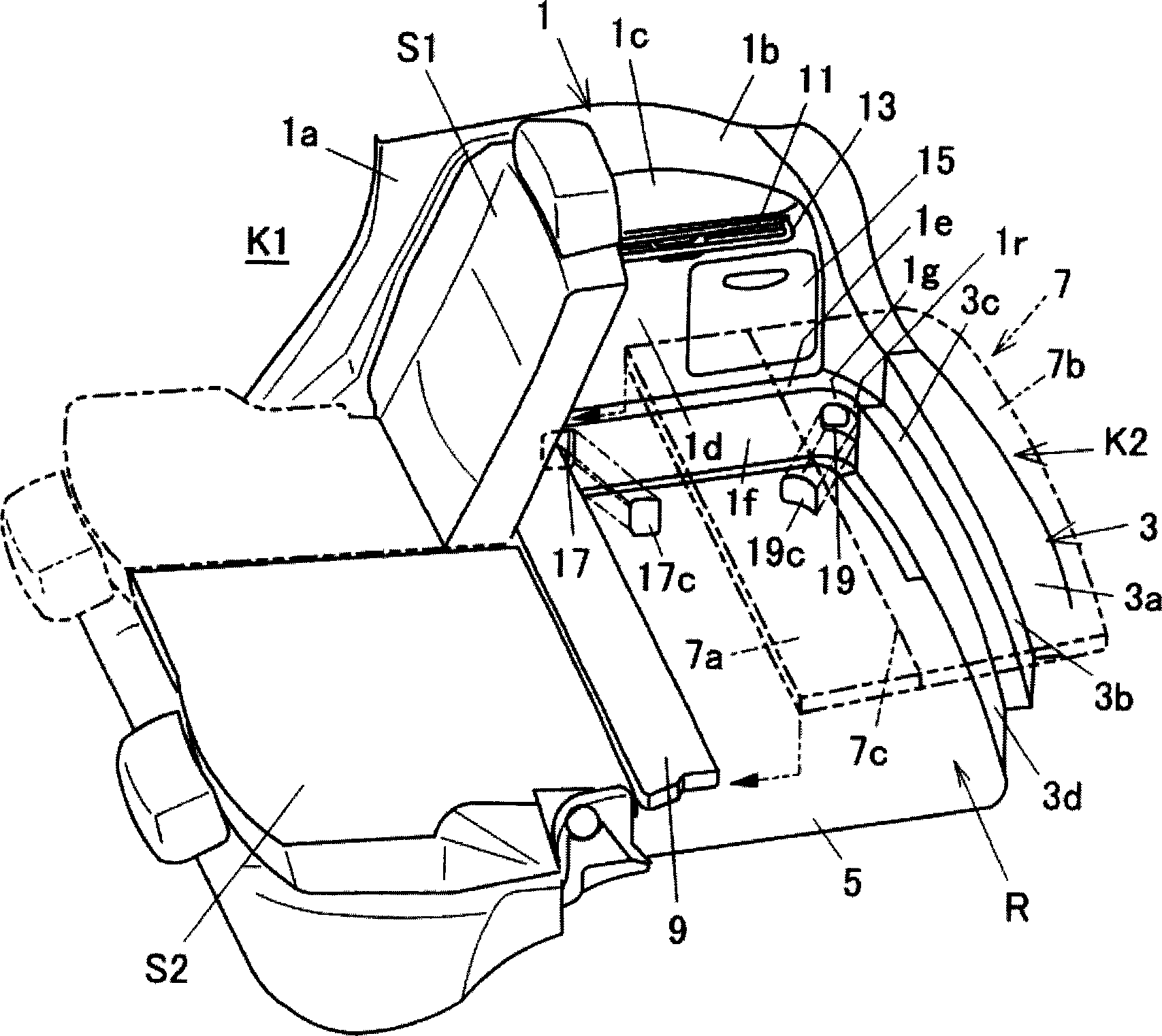
[0030] Hereinafter, best embodiments of the present invention will be described with reference to the drawings. In the drawings described below, due to the side trim forming the side of the luggage room, and the body structure such as the outer side panel of the vehicle exterior, in the figure 1 The side shown is roughly symmetrical to the other side facing that face, so only the figure 1 side shown.

[0031] figure 1 It is a perspective view of the luggage room at the rear of the automobile involved in the present invention.

[0032] Such as figure 1 As shown, a pair of rear seats S1 and S2 are arranged side by side in the vehicle width direction in the vehicle interior, and a luggage room R is formed behind the rear seats S1 and S2. The rear seats S1 and S2 adopt the foldable type, when the rear seat S1 is folded forward like the rear seat S2 (such as figure 1 Shown by the midpoint line), it is connected with the luggage room R to form a space that can carry larger lugg...


PUM


Abstract

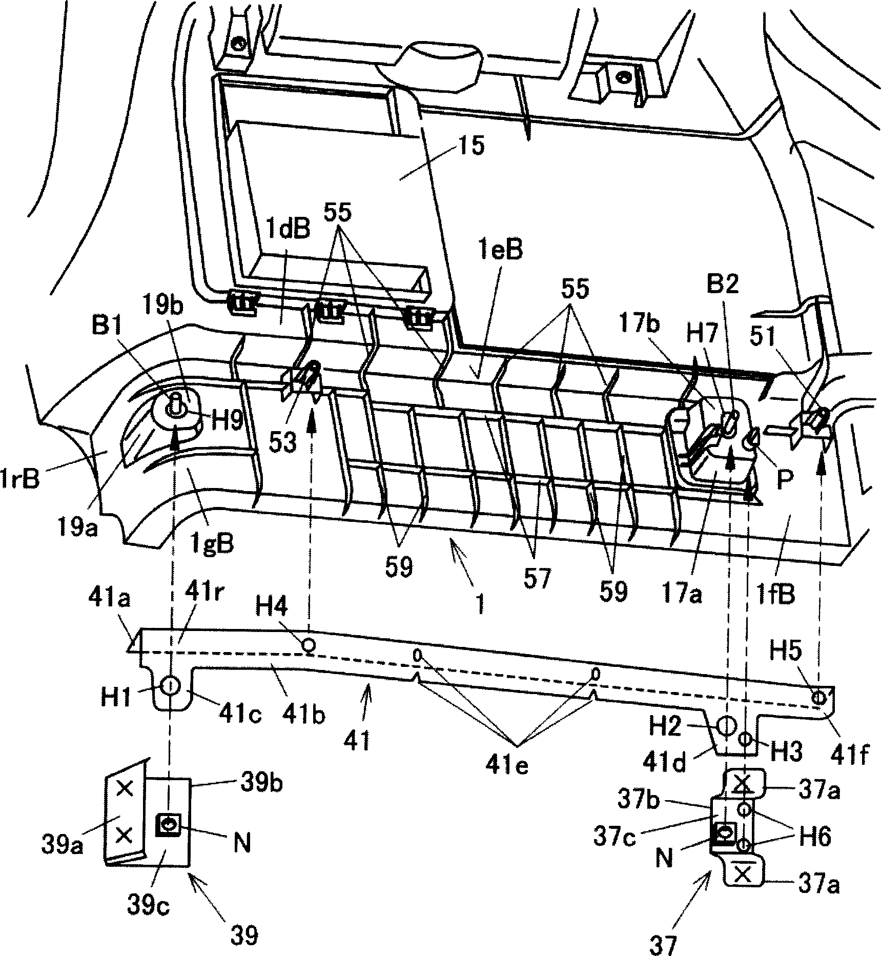
The purpose of this invention is to achieve a rear baggage compartment structure of an automobile capable of improving assembly efficiency as well as achieving both of improvement of load resistance of a trunk board and deformation suppression of a side trim. A first rack 1e is provided on the side trim 1, and the first rack 1e is continuously connected to a second rack 3c of a rear end trim 3. A plurality of ribs 55 extending downward and abutting with an upper surface 41a of a reinforcement 41 are provided on a first rack lower surface 1eB along the longitudinal direction. The side trim 1 is assembled with the reinforcement 41 in advance, and then is assembled with a first bracket 37 and a second bracket 39 fixed on the vehicle body side. Holes H7 and H9 and holes H2 and H1 into which bolts are inserted are formed on the side trim 1 and the reinforcement 41 respectively, and diameters thereof are considerably larger than a diameter of a bolt screw, and thereby adjustment of the position between the side trim 1 and the brackets 37 and 39 is adjustable.

Description

technical field [0001] The invention relates to a luggage room structure at the rear of an automobile. technical background [0002] In Japanese Patent Application Laid-Open No. 2001-328488, the structure of the trunk room at the rear of the automobile has been disclosed. In the automobile rear trunk room structure disclosed in Japanese Patent Application Laid-Open No. 2001-328488, near the lower part of the rear side window forming the side wall of the luggage room behind the rear seat of the vehicle, the wheel house part and the box-shaped A plurality of hooks are provided on the inner upper end of the component in the vehicle width direction, and the above hooks can hold the front package tray (luggage board) and the rear package tray (luggage board) (see Fig. 5). [0003] However, according to this structure, when a relatively heavy cargo is loaded on the packing tray (luggage board), since only a small portion of the packing tray in the ...

Claims


Application Information

Patent Timeline
IPC IPC(8): B60R5/04B60R13/02B62D25/08
Inventor 山际刚羽场宪昭
Owner MAZDA MOTOR CORP
Learn More