Exhaust unit of duster

A technology for exhaust devices and vacuum cleaners, applied in vacuum cleaners, cleaning equipment, household appliances, etc., can solve problems such as the decline of product credibility, achieve good cleaning effect, and improve credibility.

Inactive Publication Date: 2005-03-30
LG ELECTRONICS (TIANJIN) APPLIANCES CO LTD
View PDF0 Cites 1 Cited by
  • Summary
  • Abstract
  • Description
  • Claims
  • Application Information

AI Technical Summary

Problems solved by technology

This will lead to a decline in the credibility of the product among customers, and has even been raised as a structural problem

Method used


Image

  • Exhaust unit of duster
  • Exhaust unit of duster
  • Exhaust unit of duster

Examples


Embodiment Construction

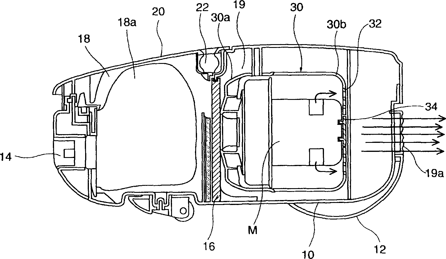
[0037] Below in conjunction with accompanying drawing and specific embodiment the present invention is described in further detail: image 3 It is a schematic diagram of the structure of the exhaust part provided by the present invention. As shown in the figure, the exhaust part 200 is formed at the rear of the case cover B1 and consists of the installation part 210 and the main body exhaust hole 230 . Wherein, the casing cover B1 covers the upper part of the main body B. The exhaust filter element 300 is installed on the mounting part 210 to filter the exhausted air. Air is exhausted outside through the main body exhaust hole 230 .

[0038] In order to surround and fix the exhaust filter element 300 , the installation part 210 protrudes from the casing cover B1 and is formed by a guide part surrounded by four sides. In addition, in order to allow the air to be exhausted only through the exhaust filter element 300 , it is preferable that there is no gap between the installa...


PUM


Abstract

An exhaust module of cleaner is composed of a fan / motor unit for generating dust sucking force, a motor casing consisting of the first half with an exhausted air guide part and the second half, and an exhaust unit on the cover of casing for exhausting air upward, preventing the dust from flying up from ground.

Description

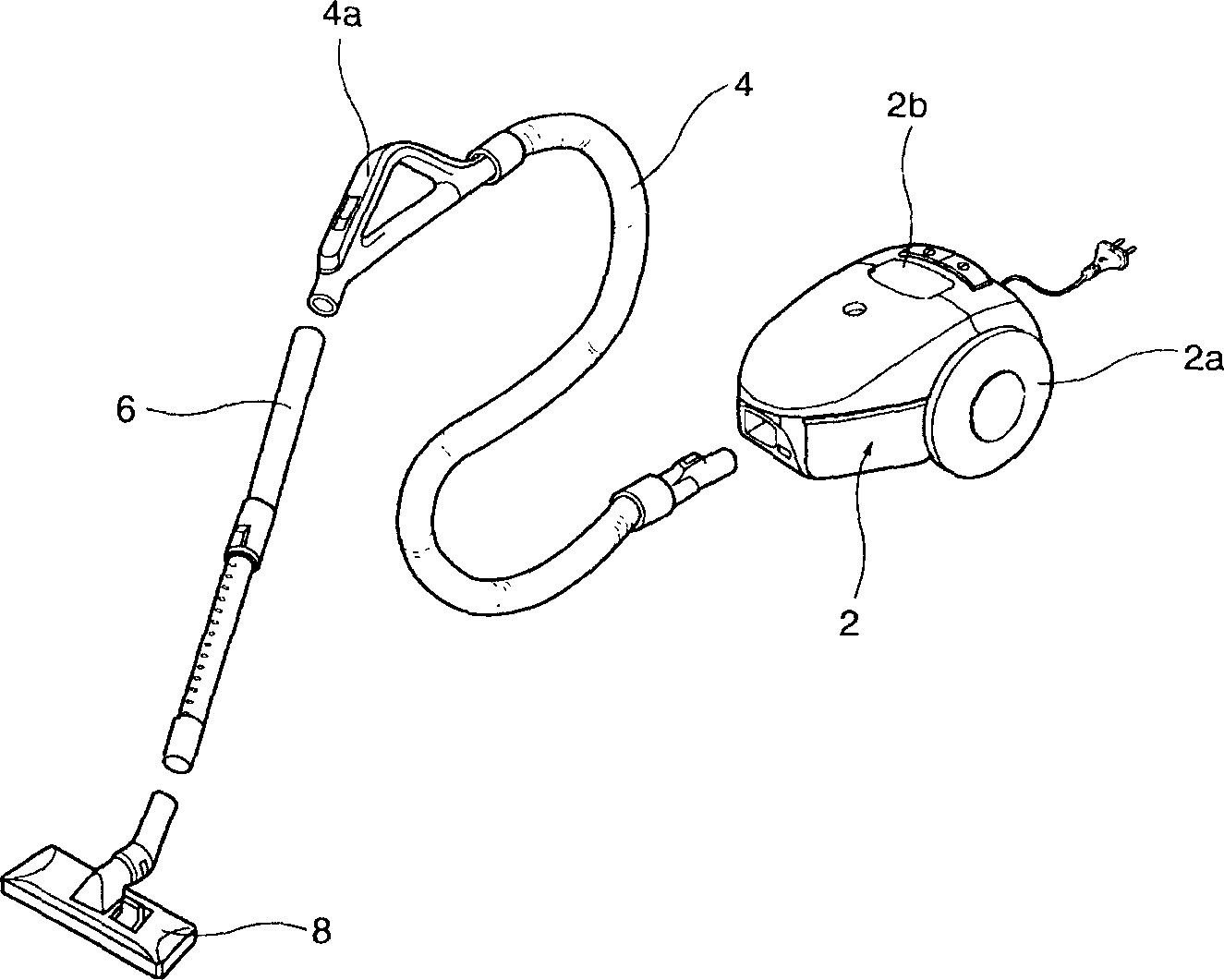
technical field [0001] The invention relates to the field of vacuum cleaners. Background technique [0002] Generally speaking, the vacuum cleaner is a household appliance that uses the strong suction generated by the rotation of the fan motor to suck in dust or foreign objects on the ground or in the crevices, and collect them in the dust bag inside the main body. [0003] Such as figure 1 As shown, the vacuum cleaner with the above functions includes a main body 2, a connecting pipe 4, a telescoping pipe 6, a dust suction head 8 and other structures. The main body 2 is provided with a motor to generate suction. The connecting pipe 4 is made of soft material and communicates with the inside of the main body 2 . The telescopic tube 6 communicates with the connecting tube 4 and can be stretched. The dust suction head 8 is combined with the end of the telescopic tube 6 and contacts the ground to suck foreign matter. In addition, the lower side of the main body 2 is provid...

Claims


Application Information

Patent Timeline
IPC IPC(8): A47L9/00
Inventor 柳明植朴泰进梁海石
Owner LG ELECTRONICS (TIANJIN) APPLIANCES CO LTD
Why Eureka
Try Eureka