New type condenser cooling structure of window air conditioner

A technology of cooling structure and condenser, which is applied in air conditioning system, prevention of condensed water, heating method, etc., and can solve problems such as unable to cool by condenser

Inactive Publication Date: 2005-03-09
LG ELECTRONICS (TIANJIN) APPLIANCES CO LTD
View PDF0 Cites 14 Cited by
  • Summary
  • Abstract
  • Description
  • Claims
  • Application Information

AI Technical Summary

Problems solved by technology

[0009] However, from the internal structure of the existing air conditioner, as the amount of condensed water (C) increases, the condensed water (C) will fall quickly due to its own weight after being taken up by the outdoor fan (11), so, Before reaching the condenser (12), most of the condensed water has fallen into the condensed water tank (20), and the condensed water brought up along with the rotation of the outdoor fan (11) will only cool the condenser (12) A part of the area, so that the entire condenser cannot be cooled

Method used


Image

  • New type condenser cooling structure of window air conditioner
  • New type condenser cooling structure of window air conditioner
  • New type condenser cooling structure of window air conditioner

Examples


Embodiment Construction

[0037] The structure of the present invention will now be described in detail with reference to the accompanying drawings.

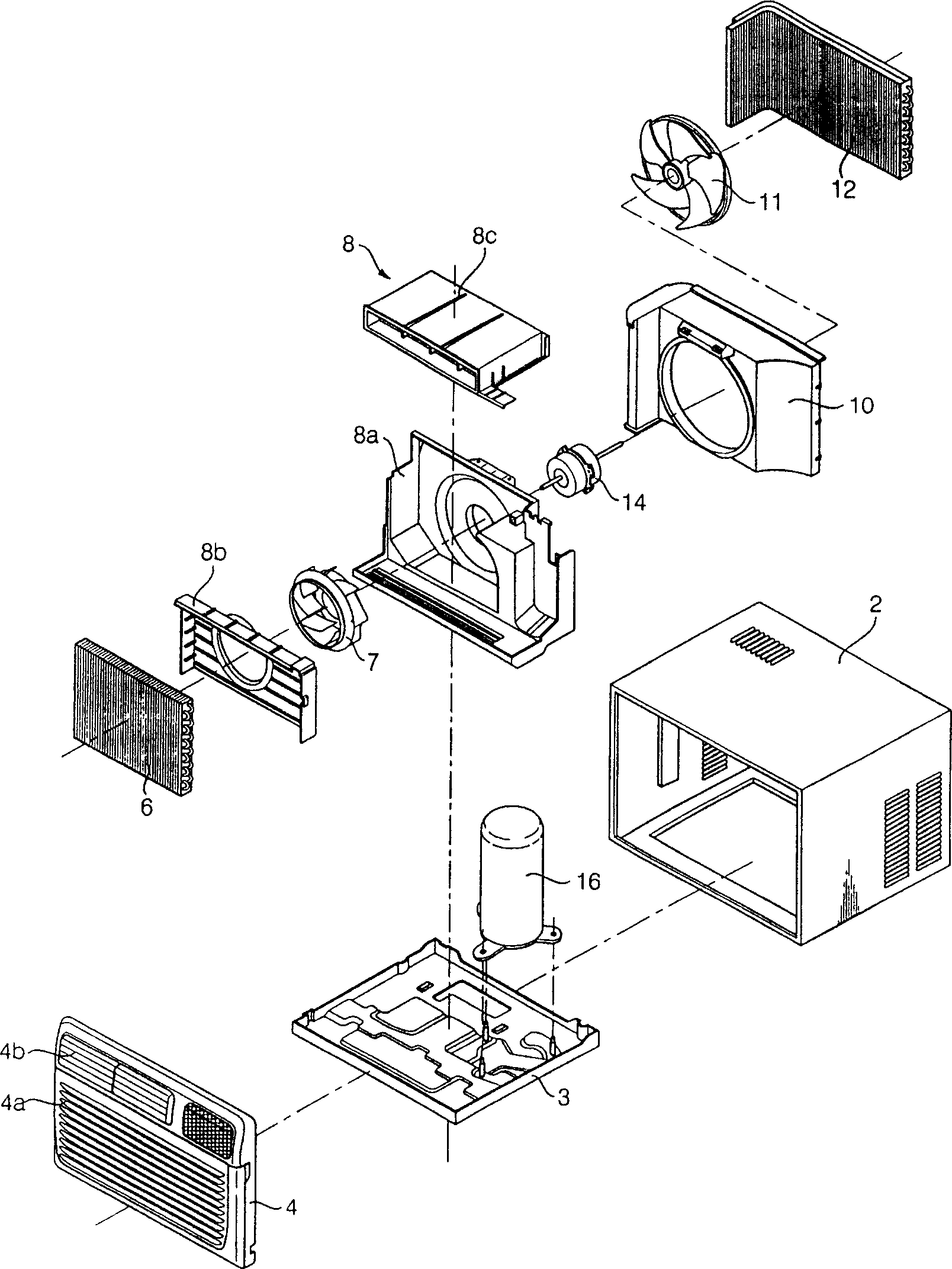
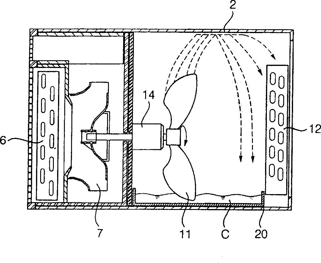
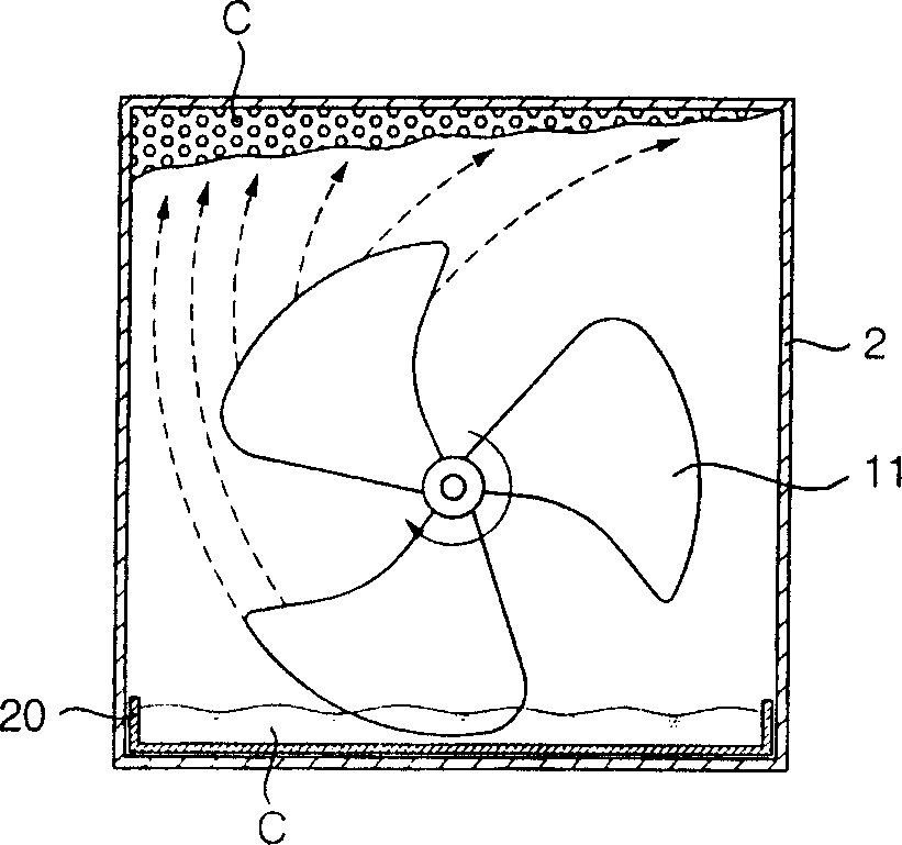
[0038] Such as Figure 4 , Figure 5 with Image 6As shown, the outside of the window air conditioner involved in the present invention is constituted by a casing (60), on which an inlet and an outlet for outdoor air are formed, and the bottom of the casing (60) is formed by The bottom plate is formed, and the front of the casing is a panel, and the intake port and the exhaust port for indoor air to enter and exit are formed on the panel. The inside of the panel is provided with the following components: evaporator (42), condensed water tank (54), outdoor fan (48), condensed water guiding device (70), indoor fan (58), air guiding device, partition (52 ), outdoor fan (48), condenser (44), motor (56), expansion valve and compressor (44). The air entering the air conditioner exchanges heat with the refrigerant through the evaporator (42). Condensed wat...


PUM


Abstract

A cooling structure of condenser for window-type air conditioner features that the condensed water generated by evaporator is used to cool the condenser, and a condensed water guider is used to apply the water to the top surface of condenser.

Description

technical field [0001] The invention relates to an air conditioner, in particular to a cooling device for a condenser of the air conditioner. Background technique [0002] Existing window air conditioners use condensed water generated on the evaporator to cool the condenser, so as to further improve the efficiency of the condenser. [0003] figure 1 It is a composition diagram of a general window air conditioner, figure 2 It is a side view of the condenser cooling structure of the window air conditioner in the prior art, image 3 It is the front view of the condenser cooling structure of the window air conditioner in the prior art. [0004] figure 1 , figure 2 with image 3 The structure of a prior art window air conditioner is shown. As shown in the figure, the outside of the air conditioner is made of a casing (2), on which an inlet and an outlet for outdoor air are formed. The lower part of the casing (2) is composed of a bottom plate (3), and in front of the ca...

Claims


Application Information

Patent Timeline
Patent Type & Authority Applications(China)
IPC IPC(8): F24F1/02F24F13/22
Inventor 李贤具
Owner LG ELECTRONICS (TIANJIN) APPLIANCES CO LTD
Why Eureka
Try Eureka