
Low noise high pressure centrifugal fan

A high-pressure centrifugal fan and low-noise technology, applied in mechanical equipment, machines/engines, liquid fuel engines, etc., can solve the problems of lack of small flow, huge processing costs, high-frequency noise, etc., and achieve a wide selection of materials and unique shapes , Noise reduction effect

Active Publication Date: 2005-03-02
浙江玖通机械科技有限公司
View PDF0 Cites 19 Cited by
  • Summary
  • Abstract
  • Description
  • Claims
  • Application Information

AI Technical Summary

Problems solved by technology

Its disadvantages: First, the structure of the forward curved blade itself determines that under the high-pressure working state, the high-frequency noise is abnormally large, which seriously pollutes the environment and endangers people's physical and mental health; second, the complex blade structure and wheel cover shape line The processing cost is huge, and it is very difficult to expand non-standard equipment; the third is the similar design theory, which makes the pressure of the product drop sharply at low flow rate, and the flow power increases sharply at high total pressure, and there is a lack of products with small flow rate and high total pressure

Method used


Image

  • Low noise high pressure centrifugal fan
  • Low noise high pressure centrifugal fan
  • Low noise high pressure centrifugal fan

Examples


Embodiment 1

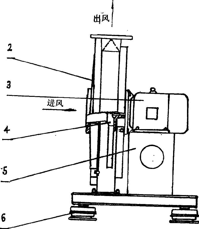
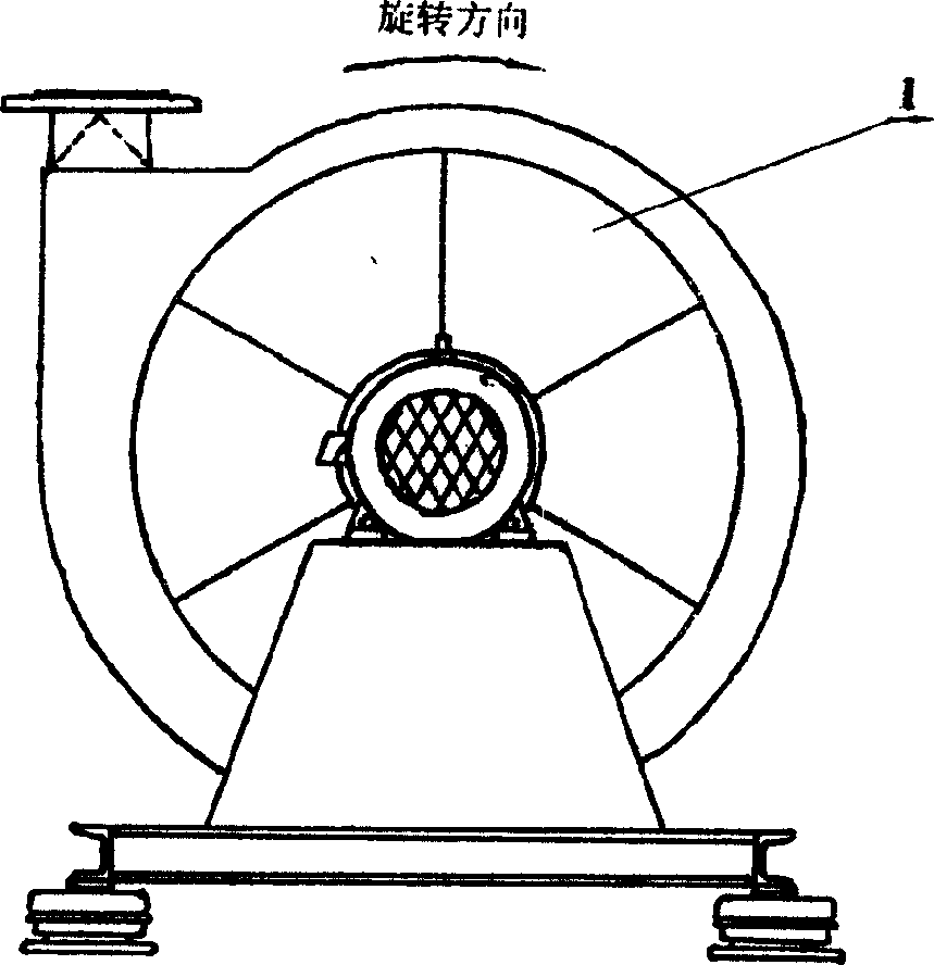
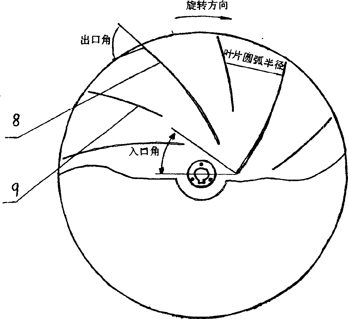
[0016] Embodiment 1: a low-noise high-pressure centrifugal fan, which includes a casing 1, an air inlet cover 2, a motor 3, an impeller 4, and a frame 5, and the motor 3 drives the impeller 4 to rotate clockwise or counterclockwise in the casing 1, The airflow is inhaled from the inlet of the air inlet cover plate 2, and the airflow flows out from the air outlet due to the suction and rejection of the impeller 4 and the regulation and guidance of the casing 1. Device 6 carries the whole machine in contact with the ground, and plays a role in attenuating the vibration of the fan, see the attached photo figure 1 and 2 . The wheel cover 6 and the wheel disc 7 in the impeller 4 form an air inlet and regulate the air flow, the wheel disc 7 is connected with the shaft disc 10, the long blades 8 and the short blades 9 are located between the wheel cover 6 and the wheel disc 7 and will Its connection, the wheel cover 6 acts as an air intake and regulates the airflow with the wheel d...


PUM


Abstract

The invention relates to low noise high pressure centrifugal fan. It includes casing, air inlet coverplate, motor, impeller and frame. Wheel disc and shaft disc are connected, long blade and short blade are fixed between cover plate and wheel disc. There are reinforced ring and rib on external side. Air inlet two ends of air inlet cover plate are connected separately with air inlet flange and cover plate. Advantages: 1) reducing noise greatly, 2) product is strong, light and beautful. 3) small flow rate.

Description

Technical field: [0001] The invention relates to a fan, which is a low-noise, high-pressure centrifugal fan and belongs to the field of centrifugal fan manufacturing. Background technique: [0002] At present, in the design of domestic high-pressure centrifugal fans, one is forward-curved blades composed of single-curved or multi-curved profiles; the other is a combination of multi-curved profiles; Similar scaling relationship; Fourth, at the same time of full high pressure, accompanied by large flow and high power. Its disadvantages: First, the structure of the forward curved blade itself determines that under the high-pressure working state, the high-frequency noise is abnormally large, which seriously pollutes the environment and endangers people's physical and mental health; second, the complex blade structure and wheel cover shape line The processing cost is huge, and it is very difficult to expand non-standard equipment; the third is similar design theory, which makes...

Claims


Application Information

Patent Timeline
Patent Type & Authority Applications(China)
IPC IPC(8): F04D17/08F04D29/30F04D29/40F04D29/66
Inventor 吴伟
Owner 浙江玖通机械科技有限公司
Learn More