
Lacrimal retractor with lighting device

The technology of a lighting device and a spreader is applied in the field of special medical equipment, which can solve the problems of affecting the operation of the operator, damage to the subcutaneous muscle tissue, and difficulty in performing the operation, and achieve the effect of shortening the operation time, clearing the operation field, and reducing the pain of the patient.

Inactive Publication Date: 2005-03-02
枝江市人民医院
View PDF0 Cites 5 Cited by
  • Summary
  • Abstract
  • Description
  • Claims
  • Application Information

AI Technical Summary

Problems solved by technology

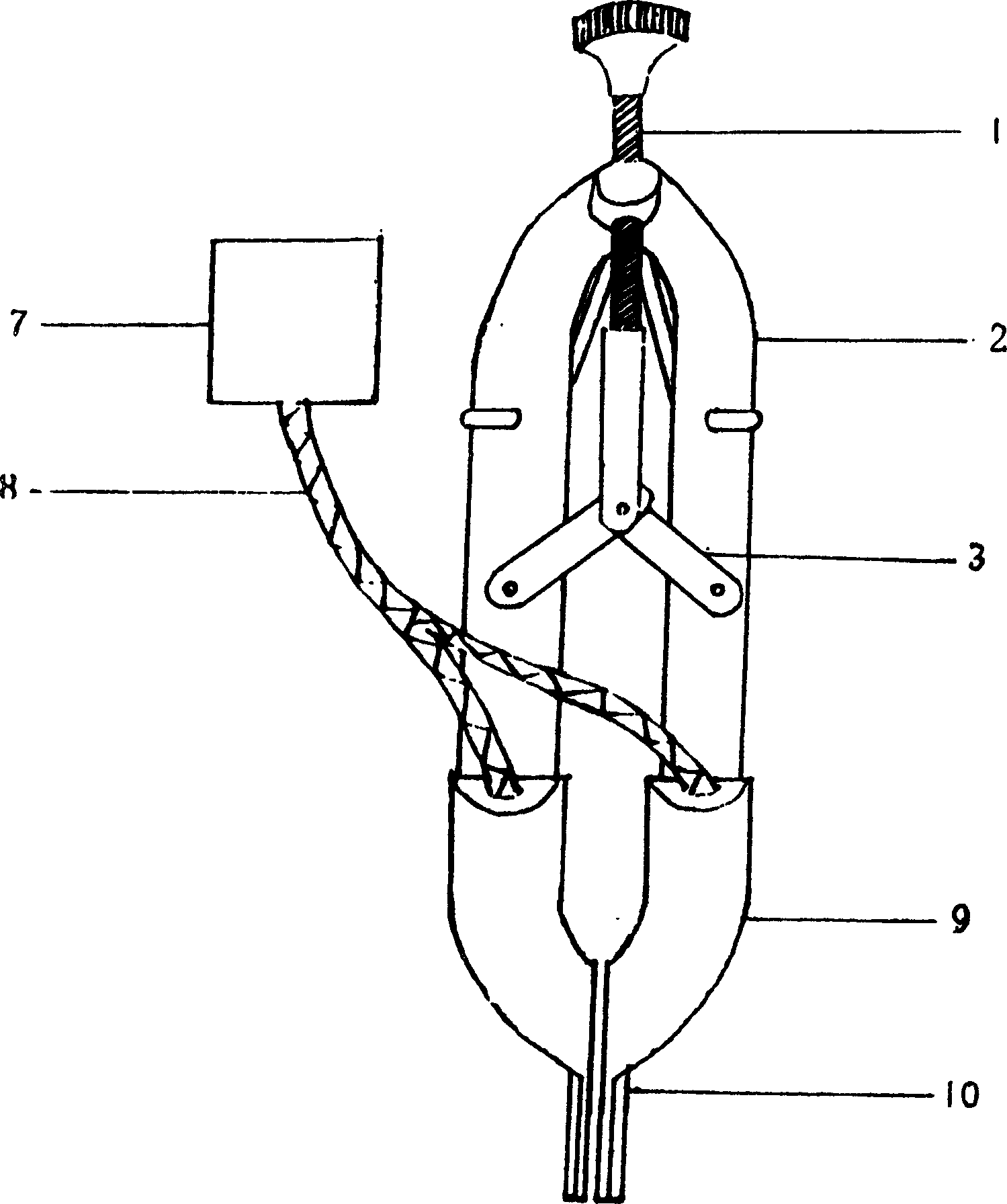
[0002] The lacrimal sac spreader is one of the indispensable and important surgical instruments in ophthalmology-related lacrimal sac surgery. The current lacrimal sac spreader is composed of a spreader mechanism composed of an adjusting screw, a forearm, a spreader connecting rod, and an arc-shaped hook. It is inconvenient to place and take out during use, and it will cause certain damage to the skin and subcutaneous muscle tissue, which will affect the incision suture after the operation.
At the same time, due to the small and deep field of view of the lacrimal sac surgery, the shadowless lamp is far away from the surgical field of view. In addition, the surgeon needs to peep at a close distance during the operation, and the head of the surgeon can also block part of the light, resulting in the obvious insufficient illumination of the deep surgical field of view, which seriously affects the operation. Operated by the operator, so the traditional operation is completed based on the experience of the operator
For example, in dacryocystorhinostomy, if the illumination of the operative field is insufficient, the operator may not be precise enough to make the hole in the lacrimal fossa of the nasal bone. If the hole is too large, it may lead to postoperative collapse of the nasal bone, seriously affecting the patient. The face is beautiful; if the position of the hole is too high, it is more likely to cause the failure of the operation; if the corresponding nasal mucosa is damaged during the hole making process, it may lead to the failure of the mucosa to match the lacrimal sac, or more bleeding, making the operation difficult
In addition, due to individual differences in patients, such as the thickness of the nasal bone, the position and size of the lacrimal fossa, and the width of the nasal cavity, if the surgical field of view is insufficiently illuminated, it may affect the success of the operation.

Method used


Image

  • Lacrimal retractor with lighting device
  • Lacrimal retractor with lighting device
  • Lacrimal retractor with lighting device

Examples


Embodiment approach

[0019] Another embodiment of the lighting device is: including a power supply 12, an electric wire 13 connected to the power supply 12, the electric wire 13 is placed in the hollow arc-shaped forearm 2, and the lighting bulb 14 is located in the forearm 2 near the end of the expansion piece 10, and the lighting bulb 14 Connect with wire 13.

[0020] The stretching piece is made of transparent materials such as plexiglass or metal materials, which play the role of bearing force. The lower edge of the spreading piece is slightly rolled up into a slightly hooked shape, and the hollow tube can be inserted into the optical fiber bundle. Or wires, the light from the cold light source is delivered to the head of the spreader through the bifurcated quartz light beam, and then shines into the deep part of the surgical field, so as to achieve good exposure of the surgical field and increase the illumination of the deep surgical field.

[0021] When in use, the present invention is place...


PUM


Abstract

The lacrimal retractor with lighting device includes retracing mechanism comprising regulating screw bolt, regulating arm with arced hollow front end and retracting link rod; retracting sheet integrated with the arced hollow front end and connected to the retracing mechanism; lighting device connected to the arced hollow front end. The rectangular retracting sheet has slightly outwards hooked low edge. The present invention has good light guiding performance, high brightness, clear operation view field for convenient handling, no heat feeling produced in the wound and other advantages.

Description

technical field [0001] The invention belongs to a medical surgical instrument, in particular to a special medical instrument for lacrimal sac-related operations. Background technique [0002] The lacrimal sac spreader is one of the indispensable and important surgical instruments in ophthalmology-related lacrimal sac surgery. The current lacrimal sac spreader is composed of a spreader mechanism composed of an adjusting screw, a forearm, a spreader connecting rod, and an arc-shaped hook. It is inconvenient to place and take out during use, and it will cause certain damage to the skin and subcutaneous muscle tissue, which will affect the incision suture after the operation. At the same time, due to the small and deep field of view of the lacrimal sac surgery, the shadowless lamp is far away from the surgical field of view. In addition, the surgeon needs to peep at a close distance during the operation, and the head of the surgeon can also block pa...

Claims


Application Information

Patent Timeline
IPC IPC(8): A61F9/007
Inventor 唐兆敏李霖鲜于树平田亚华张小妹姚凡吴江罗天玉
Owner 枝江市人民医院
Learn More