Ear picking cutting table for non-rowed corn combine

A combine harvester and header technology, which is applied in the fields of harvesters, agricultural machinery and implements, applications, etc., can solve the problems of small adaptability of corn harvesting machinery, low work efficiency, difficulty in row harvesting, etc., so as to facilitate daily maintenance, improve Efficiency, the effect of improving the efficiency of use

Inactive Publication Date: 2005-03-02
满金海 +1
View PDF0 Cites 2 Cited by
  • Summary
  • Abstract
  • Description
  • Claims
  • Application Information

AI Technical Summary

Problems solved by technology

The main reason is that most of the existing corn combine harvesters harvest in opposite rows, that is, the existing corn combine harvesters all adopt the method of picking the ear first, then cutting and crushing, and the ear picking platform must be harvested in opposite rows according to the row spacing of corn planting. , the row spacing of corn planting in various parts of our country is not the same, and it is more difficult to harvest the rows, which results in a small adaptability range of corn harvesting machinery and low work efficiency
There is a full-width corn harvester, also known as a misaligned harvester, but it is forced to help and divide the crops, and it is picked first and then cut, resulting in a large loss of ears and poor results.

Method used


Image

  • Ear picking cutting table for non-rowed corn combine
  • Ear picking cutting table for non-rowed corn combine

Examples


Embodiment 1

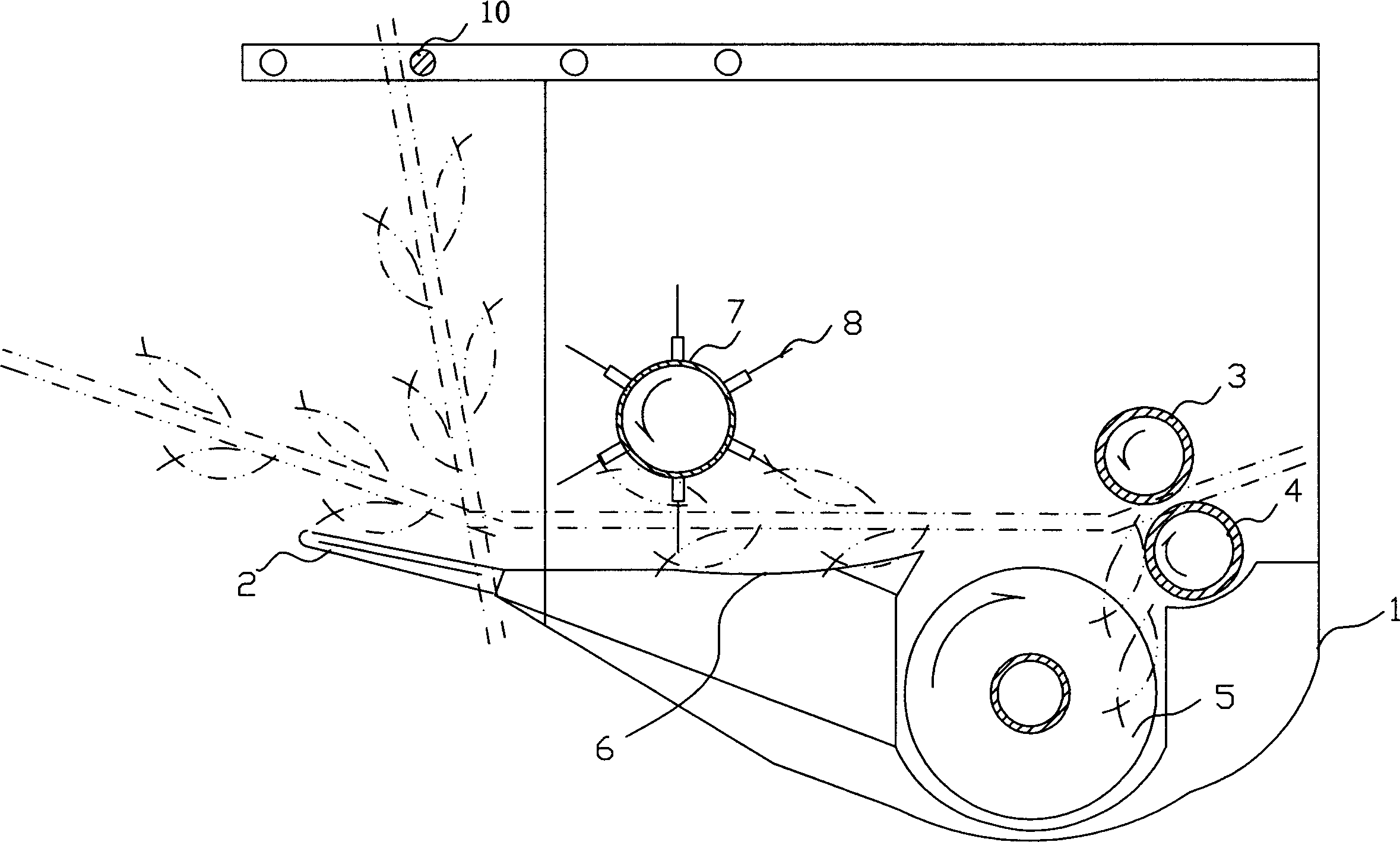
[0016] Such as figure 1 As shown, the fringe harvesting platform of the present invention includes a platform 1, a reciprocating structure cutter 2 arranged at the front end of the platform 1, and a pair of adjustable pair of rollers 3 arranged at the rear end of the platform 1 , 4 composed of the fringe picking mechanism, and the ear conveyor 5 of the auger type structure arranged between the reciprocating structure cutter 2 and the pair of rollers 3, 4, the rear end of the reciprocating structure cutter 2 is provided with a grain feeding bottom plate 6. A grain-feeding roller 7 is arranged horizontally above the grain-feeding bottom plate 6 along its transverse direction, and an elastic dial 8 is arranged radially on the peripheral surface of the grain-feeding roller 7 . On the stand 1 above the front and back of the reciprocating structure cutter 2, an adjustable pusher bar 10 is provided.

Embodiment 2

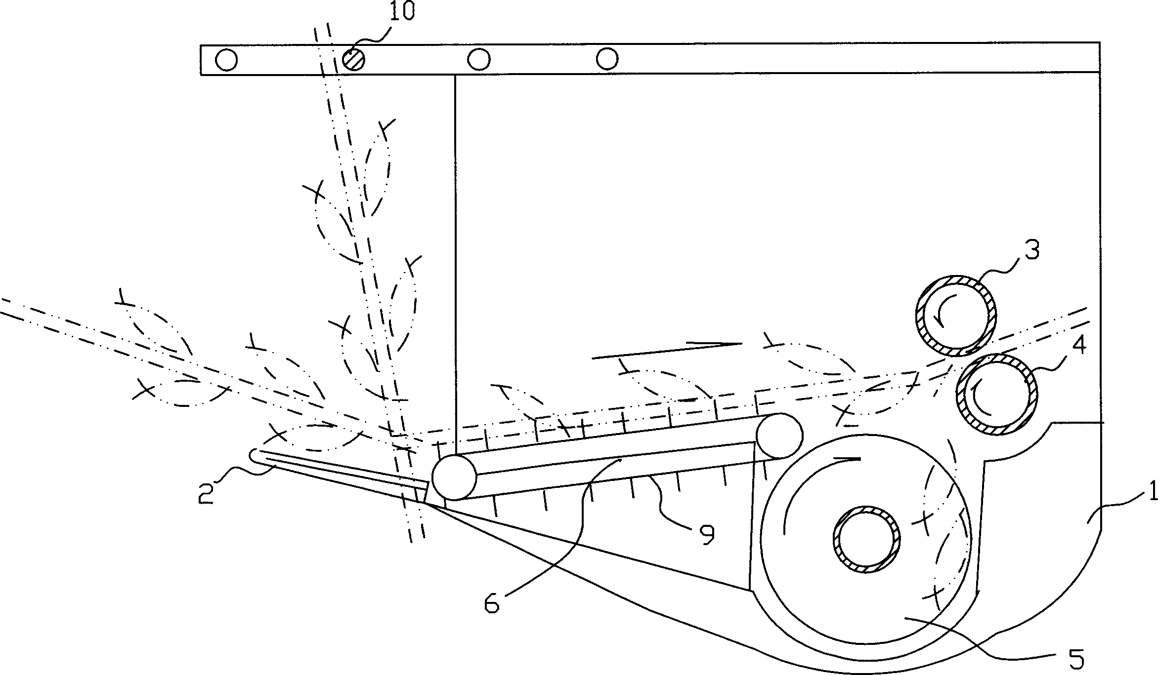
[0018] Such as figure 2 As shown, the fringe harvesting platform of the present invention includes a platform 1, a reciprocating structure cutter 2 arranged at the front end of the platform 1, and a pair of adjustable pair of rollers 3 arranged at the rear end of the platform 1 , 4 composed of the fringe picking mechanism, and the ear conveyor 5 of the auger type structure arranged between the reciprocating structure cutter 2 and the pair of rollers 3, 4, the rear end of the reciprocating structure cutter 2 is provided with a grain feeding bottom plate 6. Between the cutter 2 and the pair of rollers 3 and 4, a rotary chain rake 9 is arranged longitudinally along the grain feeding bottom plate 6; on the platform 1 above the front and upper side of the reciprocating structure cutter 2, there is a front and rear adjustable push rod 10.


PUM


Abstract

The ear picking and cutting table for non-rowed corn combine includes frame, cutter in the front end of the frame, ear picking mechanism in the back end of the frame and comprising a pair of adjustable rollers, and ear conveyer set between the cutter and the roller pair, as well as stalk conveying board set behind the cutter and stalk conveying mechanism set between the cutter and the roller pair. The present invention has the advantages of no need of regulating row pitch, the simple harvesting process including cutting plant with the cutter, feeding the plant to the ear picking mechanism, picking the ear and discharging the ear picked plant and high harvest efficiency. The ear picking and cutting table may be used in walking and back carried corn harvester.

Description

technical field [0001] The invention relates to a corn combine harvester, in particular to an ear picking header of a non-aligned corn combine harvester. Background technique [0002] Corn is the third largest crop in my country. At the current stage where the yield of wheat machine is increasing year by year and the rate of rice machine yield is increasingly recognized, the mechanized harvesting of corn has been stagnant. Most of the harvesting of corn is done manually. This has become an industry insider focus of attention. The main reason is that most of the existing corn combine harvesters harvest in opposite rows, that is, the existing corn combine harvesters all adopt the method of picking the ear first, then cutting and crushing, and the ear picking platform must be harvested in opposite rows according to the row spacing of corn planting. , the row spacing of corn planting in various parts of our country is not all the same, and the difficulty of harvesting the rows i...

Claims


Application Information

Patent Timeline
Patent Type & Authority Applications(China)
IPC IPC(8): A01D45/00A01D45/02
Inventor 满金海陈军
Owner 满金海
Why Eureka
Try Eureka