
Switching type dc-dc converter

A converter, switching technology, applied in the direction of converting DC power input to DC power output, and converting equipment and instruments with intermediate conversion to AC

Active Publication Date: 2005-02-02
ROHM CO LTD
View PDF2 Cites 14 Cited by
  • Summary
  • Abstract
  • Description
  • Claims
  • Application Information

AI Technical Summary

Problems solved by technology

Due to the F-shaped overcurrent protection feature, even if the current continues to flow, it is limited to a small current value

Method used


Image

  • Switching type dc-dc converter
  • Switching type dc-dc converter
  • Switching type dc-dc converter

Examples


Embodiment Construction

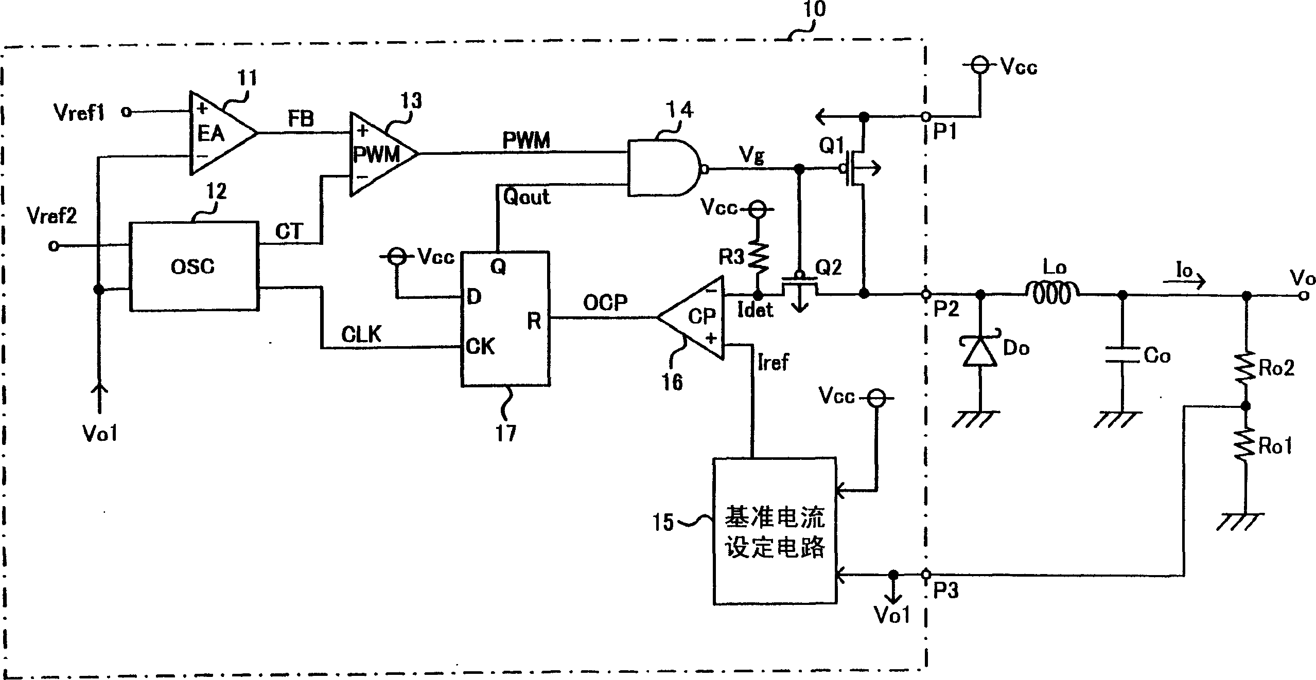
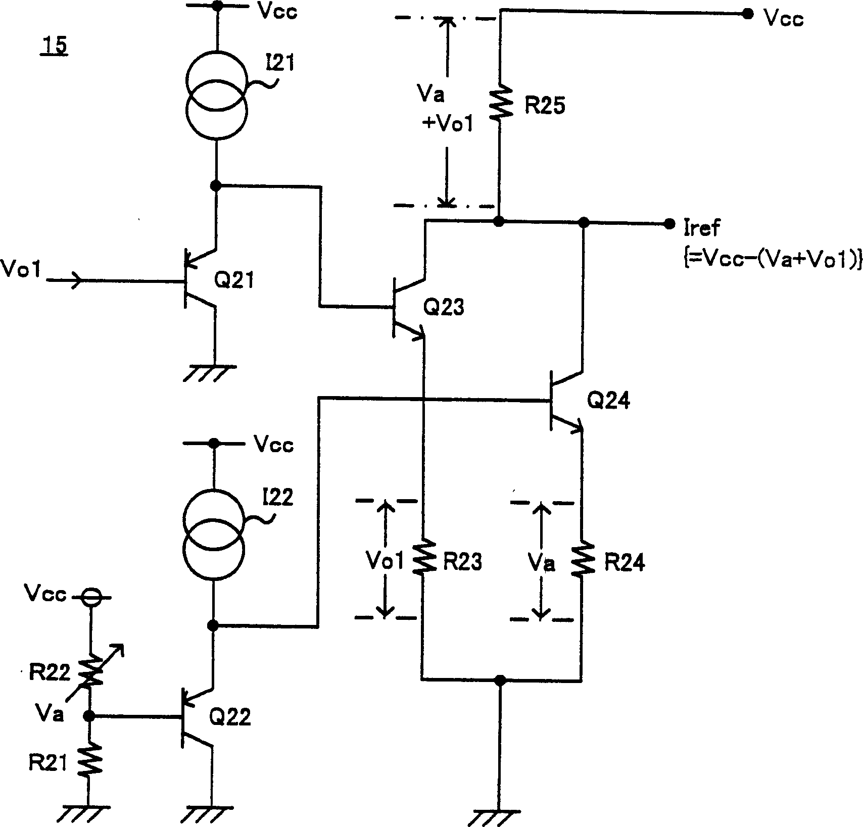
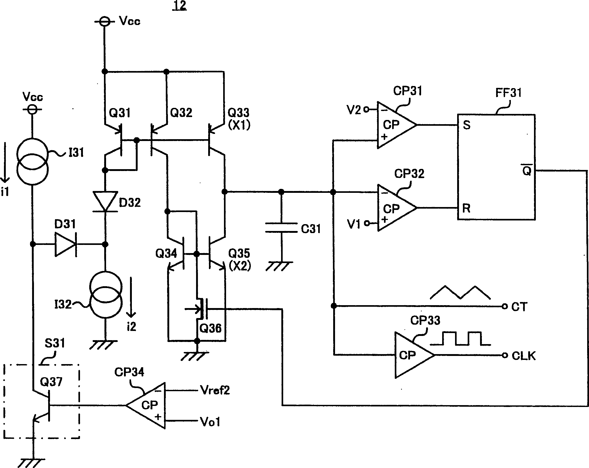
[0048] Hereinafter, embodiments of the switching DC-DC converter of the present invention will be described with reference to the drawings. figure 1 It is a configuration diagram showing the switching type DC-DC converter of the first embodiment of the present invention. figure 2 It is an example of the specific circuit configuration of the reference current setting circuit. image 3 It is an example of the specific circuit configuration of the oscillation circuit. Figure 4 It is a timing chart explaining the operation of the present invention.

[0049] figure 1 The IC10 for the mid-switching DC-DC converter is connected to the DC input voltage, that is, the power supply voltage Vcc through the first terminal P1. The DC input voltage Vcc is turned on and off by the gate control signal Vg in the switching transistor Q1, and is output from the second terminal P2. The switching transistor Q1 is a P-type MOS transistor constituting a switching transistor circuit. In addition, in ...


PUM


Abstract

Switching type DC-DC converter. To safely protect a power transistor or the like by realizing an overcurrent protection circuit of foldback current limiting characteristics with a simple configuration, related to a DC-DC converter which controls a DC input voltage by on / off switching of a power transistor for outputting a prescribed DC constant voltage. An inventive switching type DC-DC converter is adapted to set a protective reference current level lower for a decreased output voltage, and stop the switching control signal supplied to a switching transistor circuit when the detected current level exceeds the protective reference current level. In addition, in case where the output voltage declines due to, for example, a circuit failure such as short-circuiting, the switching period of the switching transistor circuit is extended. Thus, the switching type DC-DC converter is provided with a foldback current limiting type protection characteristic through reduction of the protective reference current level and extension of the switching period of cycle.

Description

Technical field [0001] The present invention relates to a switching type DC-DC converter (hereinafter referred to as a DC-DC converter) with an overcurrent protection function and capable of outputting a regulated voltage. Background technique [0002] A DC power supply device with an overcurrent protection function that limits the output to a specified current value while generating a DC constant voltage of a certain value after converting the DC input voltage has been widely used. [0003] One such overcurrent protection function uses a droop type characteristic that lowers the output voltage-output current characteristic when the current value is specified. Although this droop-type overcurrent protection is feasible, when the specified value of current continues to flow, the power transistor may be damaged due to heat. [0004] As a circuit that avoids the disadvantage of drooping characteristics, an overcurrent protection circuit with fold-back cuurent limiting (fold-back cuu...

Claims


Application Information

Patent Timeline
Patent Type & Authority Applications(China)
IPC IPC(8): H02M3/155H02H9/02H02M3/156H02M3/28
CPCH02M3/156H02M2001/0025H02M1/32H02M1/0025H02M3/28H02H9/02
Inventor 后藤大祐安藤弘明
Owner ROHM CO LTD
Learn More