


Quick Research
Generate reliable direction feasibility study reports for your R&D in just a few steps.

Technical Q&A
Discover and master advanced knowledge NOW. Basics, ideas, possibilities, all at once.

Find Solutions
As an expert in R&D theories, this can generate solutions to your technical problems instantly.

Evaluate Feasibility
Analyze your overall solution with one click, know your potential R&D risks in advance.

Monitor Landscape
Get weekly tech updates, stay abreast of the latest tech innovations and key insights.
Refractive image display device
An image display and image technology, applied in optical components, optics, instruments, etc., can solve problems such as retinal detachment and human eye discomfort, and achieve the effects of reducing loss, improving brightness and clarity
- Summary
- Abstract
- Description
- Claims
- Application Information
AI Technical Summary
Problems solved by technology
Method used
Image


Examples
Embodiment Construction
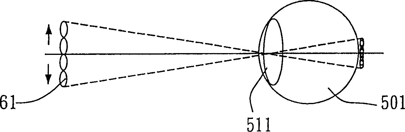
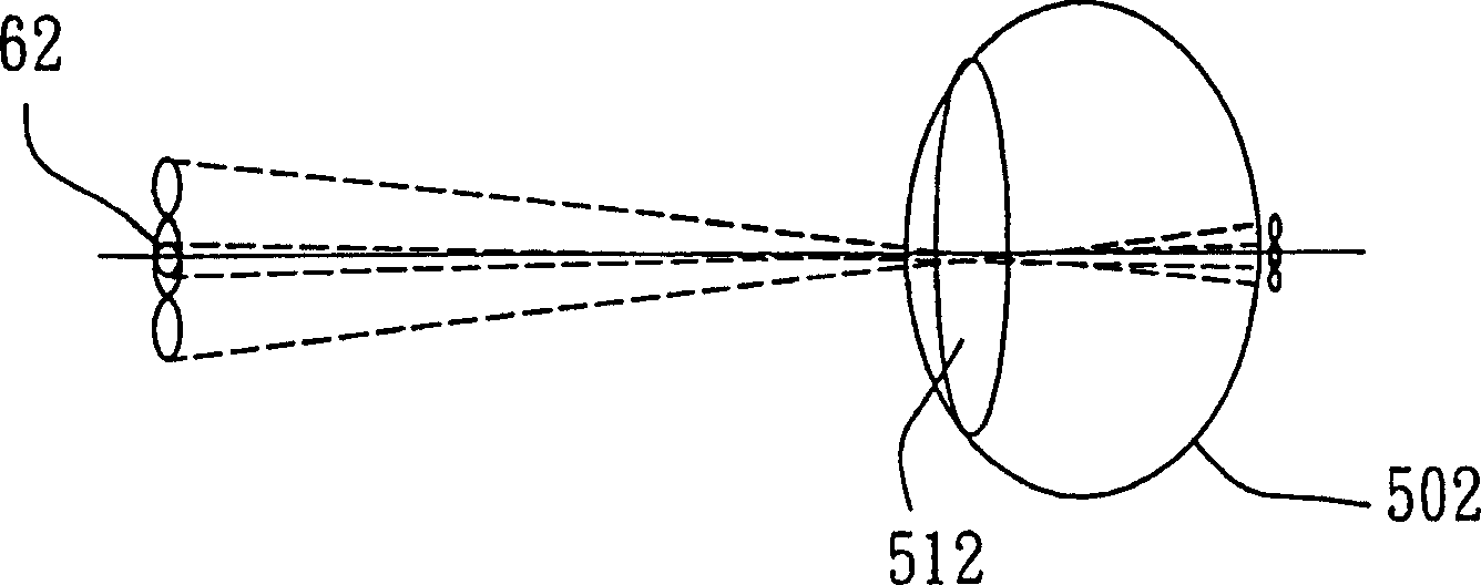
[0021] Please see first figure 2 and Figure 3a , 3b, 3c, this figure 4 is a schematic diagram of the difference between the real image and the virtual image of the eye imaging. figure 2 In the case of the real image 4 projected by the existing projection system, when the eyes regard it as a real image, the eyes must adjust the focus correctly so that the image is imaged on the retina in order to "see" the image 41, and as mentioned in the previous paragraph, The process of focusing puts strain on the eyes. Figures 3a to 3c It is the situation that the eyes of the present invention regard it as a virtual image. In this case, when the imaging mirror group (concave mirror) 260 is transparent, the real image 42 projected by the display unit (not shown) will form a virtual image 43 behind the imaging mirror group 260, and because the human eye When observing the virtual image on the reflective surface, the eyeball adjusts its focus on the reflective surface. Therefore, when ...
PUM
 Abstract
Description
Claims
Application Information
 - R&D Engineer
- R&D Manager
- IP Professional
- Industry Leading Data Capabilities
- Powerful AI technology
- Patent DNA Extraction
Browse by: Latest US Patents, China's latest patents, Technical Efficacy Thesaurus, Application Domain, Technology Topic, Popular Technical Reports.
© 2024 PatSnap. All rights reserved.Legal|Privacy policy|Modern Slavery Act Transparency Statement|Sitemap|About US| Contact US: help@patsnap.com