
Protective circuit

A technology for protecting circuits and being protected, which is applied to circuits, emergency protection circuit devices, circuit devices, etc., and can solve problems such as high manufacturing costs, difficulty in miniaturization, and large number of components

Inactive Publication Date: 2005-01-12
DEXERIALS CORP
View PDF4 Cites 2 Cited by
  • Summary
  • Abstract
  • Description
  • Claims
  • Application Information

AI Technical Summary

Problems solved by technology

[0019] In addition, there are problems such as difficulty in miniaturization and high manufacturing cost due to the large number of parts in the conventional protection element.

Method used


Image

  • Protective circuit
  • Protective circuit
  • Protective circuit

Examples


Embodiment 1

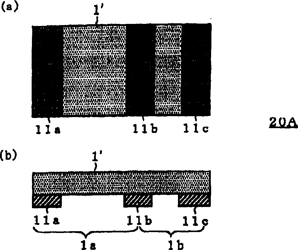
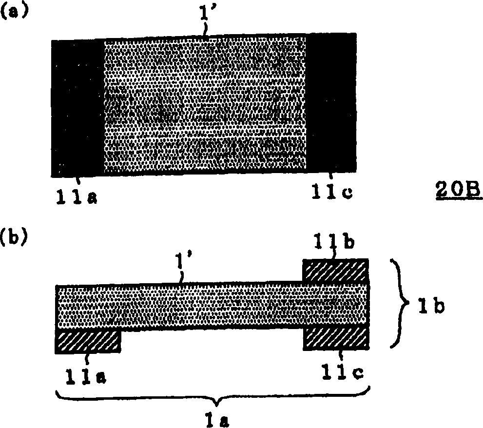
[0053] production Figure 4 protection components of the composition shown. At this time, a polymer PTC is used as the PTC material 1', and its size is 9 mm x 3 mm x 0.3 (thick). The electrode is made of 3mm×1.5mm by sputtering.

[0054] The obtained PTC element 20C had 300 mΩ between the first electrode 11 a and the second electrode 11 b (the first PTC element 1 a ), and 30 mΩ between the second electrode 11 b and the third electrode 11 c (the second PTC element 1 b ).

[0055] When the PTC element 1a and the PTC element 1b flow current in parallel, the PTC element 1a and the PTC element 1b are simultaneously disconnected at 5A. On the other hand, when a current is supplied only to the PTC element 1a, the PTC element 1a is disconnected at 0.8A.


PUM


Abstract

A protective element includes at least three electrodes provided on one PTC material. The PTC material operates as at least two PTC elements. This protective element can be manufactured, with fewer components, in an easy manner, and at lower cost, and can cope with overcurrent and overvoltage.

Description

[0001] This application is a divisional application of: [0002] Invention name: protection element [0003] Application date: July 28, 2000 [0004] Application number: 00122242.2 technical field [0005] The invention relates to a protection circuit, which protects the circuit to be protected when there is an overcurrent or overvoltage by using the disconnection of a PTC element. Background technique [0006] It is well known that current fuses, which are made of low-melting-point metals such as lead, tin, and antimony, are blown due to heat generated by overcurrent, as protection elements for blocking overcurrent to a protected circuit. [0007] Also, a PTC (Positive Temperature Coefficient: Positive Temperature Coefficient) element is known as an element that generates heat during an overcurrent, thereby increasing resistance, and controls the current flowing in a protected circuit. [0008] Furthermore, there has been proposed a protection device that combines these ...

Claims


Application Information

Patent Timeline
IPC IPC(8): H01C7/00H01C1/14H01C7/02H02H7/18H02H9/02H02H9/04
CPCH01C7/02H02H9/026H01C1/1406H02H9/042H01C7/00
Inventor 古田和隆岩崎则和
Owner DEXERIALS CORP
Learn More