
Safety valve

A safety valve and elastic sealing technology, which is applied in the field of safety valves, can solve problems such as external impact on the valve connection, falling of the bottle body, and gas leakage from gas appliances.

Pending Publication Date: 2021-10-29
广东宝缘新能源科技有限公司
View PDF0 Cites 0 Cited by
  • Summary
  • Abstract
  • Description
  • Claims
  • Application Information

AI Technical Summary

Problems solved by technology

[0002] Bottled gas is small and flexible, easy to use, and widely used. Because of its wide use, it is often used unsafely. It often happens that the bottle body falls or the valve connection is subjected to external force impact, and gas leakage occurs in gas appliances.
Gas leakage can easily cause fire and explosion. The general process is that the gas that slowly leaks into the space reaches the ignition point and starts to catch fire. After the fire, the high temperature makes the connecting hose melt or the gas valve leaks and then leaks more gas, which then leads to an explosion. or more intense fire
In order to solve this problem, there is a gas valve that can automatically break the circuit at high temperature. However, the gas valve can only play a role after the gas valve itself is burned and the temperature rises. In actual situations, the installation position of the gas valve is often difficult. In the case of being burned, even if the gas leaks and causes a fire, the temperature of the gas valve does not reach the value of the circuit breaker because the gas valve is not burned, resulting in the phenomenon that the gas valve that automatically breaks the circuit at this high temperature still fails

Method used


Image

  • Safety valve
  • Safety valve
  • Safety valve

Examples


Embodiment Construction

[0066] The present invention will be described in detail below in conjunction with the accompanying drawings.

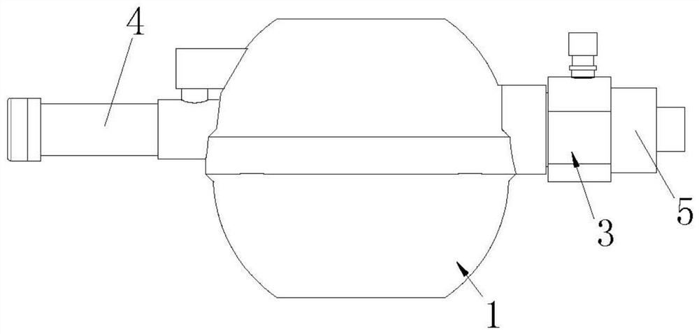
[0067] like Figure 1-10 As shown, a safety valve of the present invention includes an elastic sealing chamber structure 1, and the elastic sealing chamber structure 1 includes a base seat 11, an elastic sealing gasket 13, a sealing chamber spring 14 and an installation bowl 15, and the base seat 11 is provided with There is a plane base part 111, and the plane base part 111 is arched upwards to form an air channel 12. The elastic sealing gasket 13 is provided with a horizontal part 131, a ring edge part 132 of the sealing ring and a connecting ring edge part 132, a horizontal part 131 The conical surface deformation part 133; the horizontal part 131 and the ring edge part 132 of the sealing ring are not on the same horizontal plane; the outer edge of the plane base part 111 extends downward to form an annular boss 112, and the annular boss 112 is recessed inward to ...


PUM


Abstract

The invention relates to the technical field of valves, in particular to a safety valve. The safety valve comprises an elastic sealing chamber structure, a lever on-off structure, an over-current line breaking device, a ball piston on-off structure and a breakable connecting structure, the elastic sealing chamber structure comprises a base body seat, an elastic sealing gasket, a sealing chamber spring and a mounting bowl body, the base body seat is provided with a plane base body part, and the plane base body part and the elastic sealing gasket are jointly limited to form an elastic sealing chamber. The lever on-off structure comprises an air tap piece, a transmission lever and an on-off sliding plug, the on-off sliding plug is arranged on a sliding pipe part in a sliding mode, one end of the on-off sliding plug is connected with one end of the transmission lever, and an up-down floating piece providing power for rotation of the transmission lever is further included. The over-current line breaking device comprises a floating ball, a ball chamber, an elastic recovery piece and a buffer storage chamber. According to the safety valve, when downstream gas leakage occurs, automatic line breaking can be achieved, excessive gas leakage is avoided, and the safety protection function is achieved.

Description

technical field [0001] The invention relates to the technical field of valves, in particular to a safety valve. Background technique [0002] Bottled gas is small and flexible, easy to use, and widely used. Because of its wide use, it is often used unsafely. It often happens that the bottle body falls or the valve connection is subjected to external force impact, and gas leaks from gas appliances. Gas leakage can easily cause fire and explosion. The general process is that the gas that slowly leaks into the space reaches the ignition point and starts to catch fire. After the fire, the high temperature makes the connecting hose melt or the gas valve leaks and then leaks more gas, which then leads to an explosion. or more severe fires. In order to solve this problem, there is a gas valve that can automatically break the circuit at high temperature. However, the gas valve can only play a role after the gas valve itself is burned and the temperature rises. In actual situations,...

Claims


Application Information

Patent Timeline
Patent Type & Authority Applications(China)
IPC IPC(8): F16K17/00F16K17/40F16K1/00F16K1/14F16K31/22F16K31/165
CPCF16K17/00F16K17/40F16K1/00F16K1/14F16K31/22F16K31/165
Inventor 牛炳飞
Owner 广东宝缘新能源科技有限公司
Learn More