Liquid crystal shutter device

A technology of liquid crystal shutters and liquid crystals, applied in printing, optics, instruments, etc., can solve problems such as uneven band images, complex optical systems, and increased printing time

Inactive Publication Date: 2004-12-29
CITIZEN WATCH CO LTD
View PDF1 Cites 0 Cited by
  • Summary
  • Abstract
  • Description
  • Claims
  • Application Information

AI Technical Summary

Problems solved by technology

[0023] In addition, even for other pixels in the R pixel row, when changing the gray scale of the G pixel row connected to the extraction electrode near the pixel, the transmittance will deviate from the target value in the same way.
Such a deviation becomes a banded image unevenness on the image paper
In addition, the same problem occurs between the second color pixel (G pixel) and the third color pixel (B pixel), and these also become band-like unevenness.
[0024] The banded image is uneven, especially when the pixels of each color are separated. Although it is not obvious when approaching, the unevenness still remains
Moreover, if the pixels of each color are arranged close to each other, color separation becomes difficult and the optical system becomes complicated.
Especially when increasing the amount of light, it is difficult to approach the design due to the large size of the light source
[0025] Namely: in Figure 28 ~ Figure 30 In the conventional liquid crystal shutter device as shown, if a signal is applied to the pixels in the central pixel column, there is a problem that the light transmittance of the pixels in the two outer pixel columns is greatly affected.
[0026] Here, if a matrix-type liquid crystal shutter device is used, the influence of unevenness as described above can be reduced. However, the response speed and contrast decrease, which becomes the cause of increased printing time and decreased image quality.
In addition, it is necessary to make the light sources of various colors close to each other, which will cause interference of light sources and color mixing.
In order to prevent color mixing, even if the light sources are illuminated in sequence, for example, red, green, and blue are illuminated in proportion to the time, compared with printing with the light sources illuminated at the same time, the printing time or the instability of the light intensity of the light sources increases.

Method used


Image

  • Liquid crystal shutter device
  • Liquid crystal shutter device
  • Liquid crystal shutter device

Examples


no. 1 approach

[0076] (the first embodiment: Figure 1 to Figure 7 )

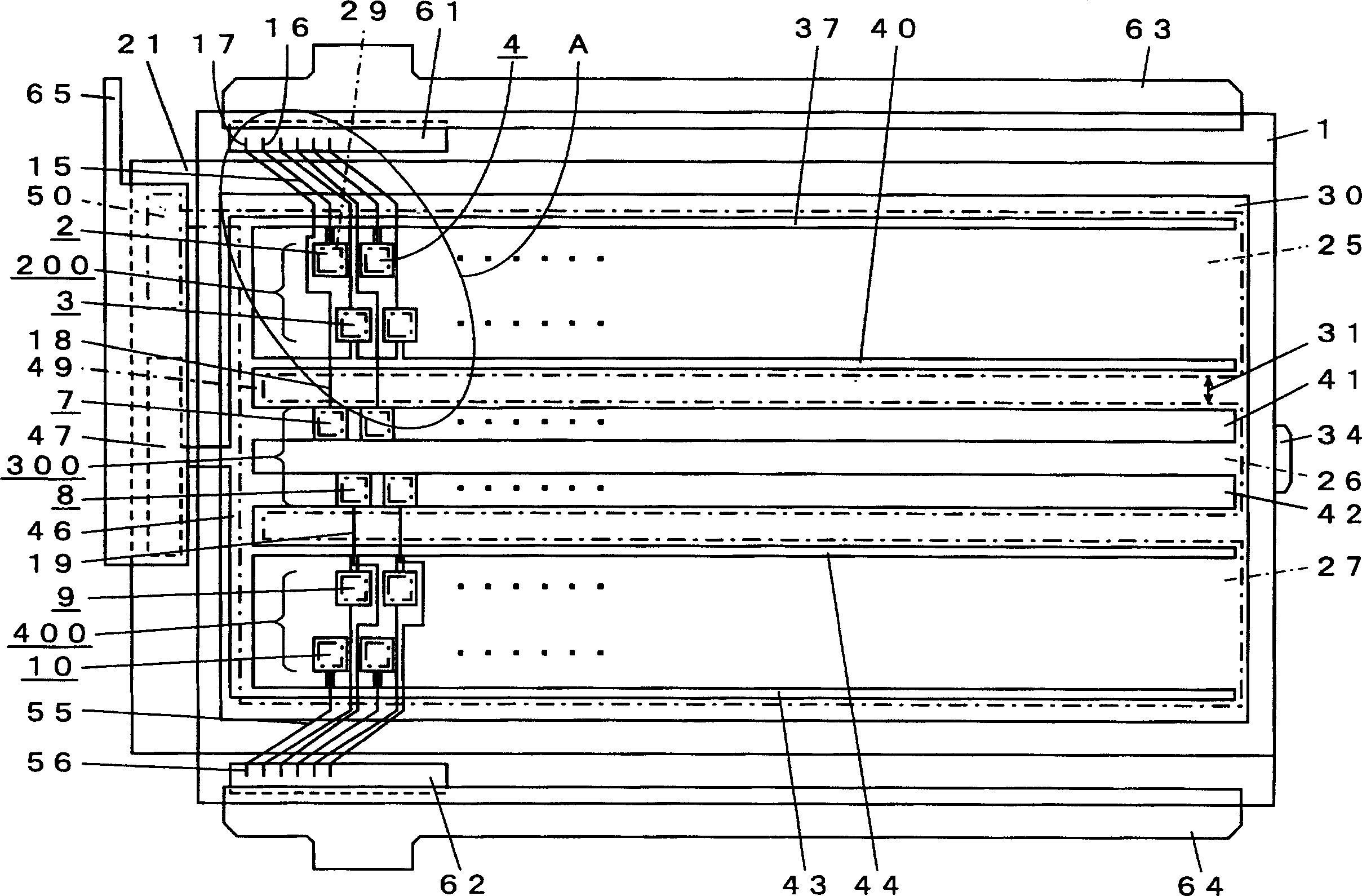
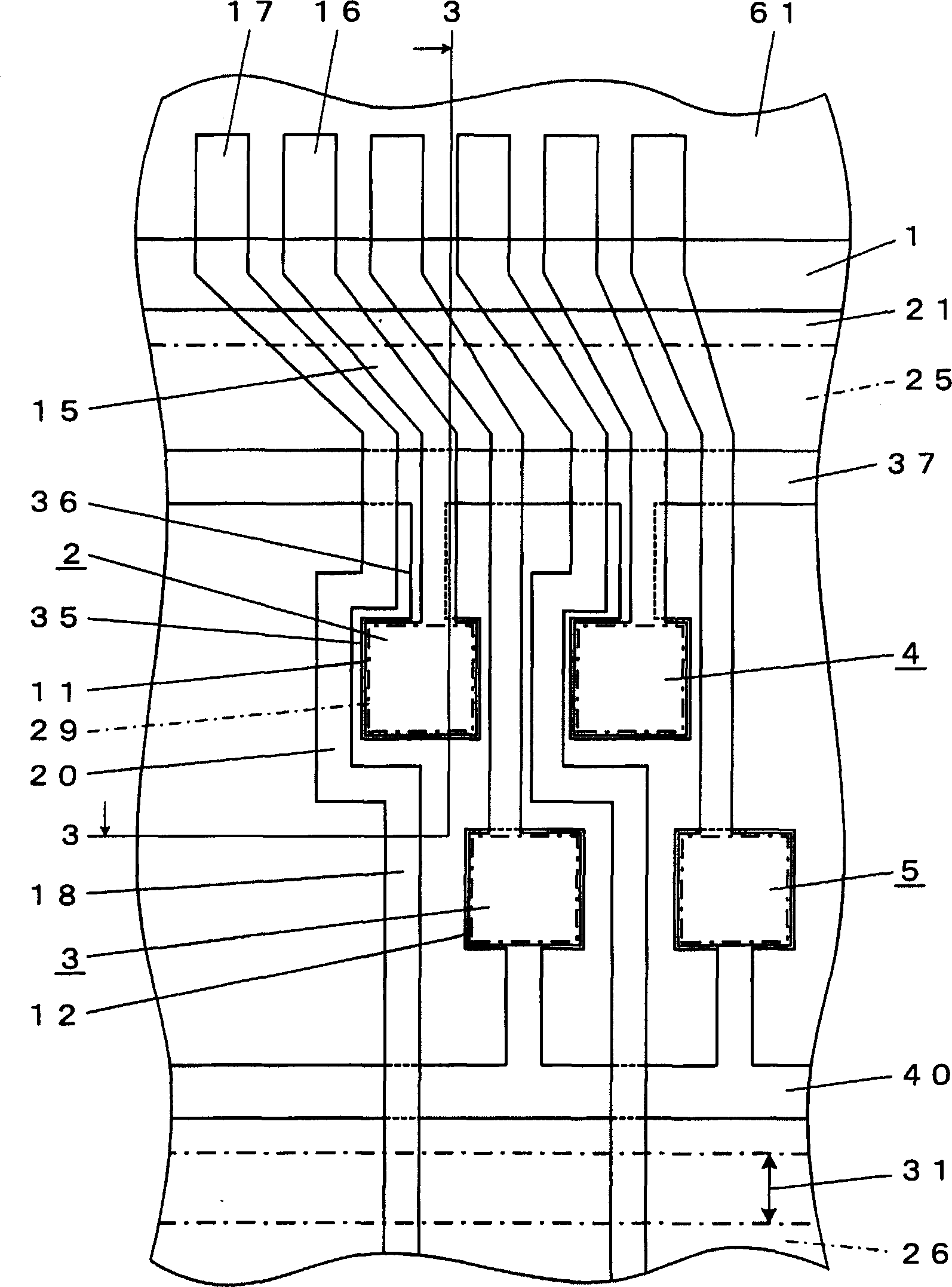
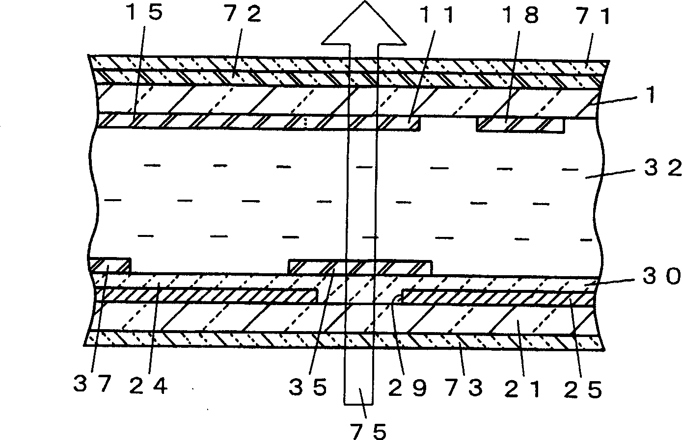
[0077] First, a first embodiment of the liquid crystal shutter device of the present invention and an optical printer including the liquid crystal shutter device will be described. figure 1 is a plan view for explaining the arrangement of electrodes and light-shielding films in the liquid crystal shutter device, figure 2 is zoomed in figure 1 A partial plan view of a part of the ellipse A, image 3 is shown along figure 2 A partial sectional view of a part of the 3-3 line section, Figure 4 It is a schematic diagram for explaining the operation of the optical printer described above. Figure 5 is along Figure 4 The schematic cross-section of the 5-5 line, Image 6 is shown for driving figure 1 The diagram showing the drive signal of the liquid crystal shutter device, Figure 7 It is a figure for demonstrating the characteristic of this liquid crystal shutter device. In these drawings, pixels are shown much...

no. 2 Embodiment approach

[0122] (the second embodiment: Figure 8 to Figure 11 )

[0123] Hereinafter, a second embodiment of the liquid crystal shutter device of the present invention will be described. Figure 8 is a partial plan view for explaining the arrangement of electrodes and light-shielding films in the liquid crystal shutter device, Figure 9 are also containing sealing material or insulating film, magnifying Figure 8 Part of the partial floor plan shown, Figure 10 is omitted in Figure 9 diagrams containing sealant and insulating film illustrations, Figure 11 is shown along Figure 9 A partial cross-sectional view of the sectional part of line 11-11. exist Figure 8 , the FPC connected to the liquid crystal shutter device is omitted from the illustration. In these figures, the parts corresponding to the configuration described in the first embodiment are given the same reference numerals.

[0124] This is because the liquid crystal shutter device is different from the first emb...

no. 4 Embodiment approach

[0151] (the 4th embodiment: Figure 15 )

[0152] Next, a fourth embodiment of the liquid crystal shutter device of the present invention will be described. Figure 15 is used to explain the electrode and light-shielding film configuration of this liquid crystal shutter device, and Figure 12 Corresponding local plan. In this figure, the parts corresponding to the configurations described in the first to third embodiments are given the same reference numerals.

[0153] Since this liquid crystal shutter device differs from the liquid crystal shutter device of the third embodiment only in that the sealing material 93 between the contours is provided near the sealing material 33, and in that narrow portions are provided on both the focusing electrode and the extraction electrode, only these point to explain.

[0154] In this liquid crystal shutter device, an inter-profile sealant 93 is provided on the inside of the sealant 33 and on the outside of the region where the insulat...


PUM


Abstract

A liquid crystal shutter device is provided with a liquid crystal cell including a first substrate (1), a second substrate (21), and liquid crystal sandwiched therebetween, pixel electrodes (11, 12) which are signal electrodes and lead-out electrodes (15) provided on the first substrate (1), counter electrodes which are common electrodes facing the pixel electrodes, provided on the second substrate (21), and a plurality of pixel rows (200, 300, 400) which are composed of pixels (2, 3, 4, etc.) formed by overlapped portions of the pixel electrodes and the counter electrodes, and the liquid crystal shutter device controls light applied to a photosensitive member continuously and relatively moving in a direction orthogonal to the pixel rows, in which the counter electrodes are provided separately for the respective pixel rows. Further, an RGB coupling electrode (46) for electrically connecting the counter electrodes of the respective pixel rows is preferably provided.

Description

technical field [0001] The present invention relates to a liquid crystal shutter device that controls light transmittance for each pixel by an electric signal, and particularly relates to an optical printer device that forms a color image on a photosensitive member by controlling the irradiation of light to a photosensitive member that is continuously relatively moved LCD shutter device. technical background [0002] In recent years, image printing apparatuses for printing images displayed on digitally processed monitors on data recording sheets have become widespread. In addition, there are thermal method, inkjet method, laser beam scanning method, liquid crystal shutter method, etc. among the printing methods of image printing apparatuses, however, among them, since the liquid crystal shutter method is suitable for miniaturization, light weight has attracted attention. [0003] The so-called liquid crystal shutter method refers to the method of forming an image on the pho...

Claims


Application Information

Patent Timeline
Patent Type & Authority Applications(China)
IPC IPC(8): B41J2/465G02F1/1343G02F1/1345
CPCG02F1/134309B41J2/465G02F1/1345G02F2201/121
Inventor 关口金孝增渕贞夫
Owner CITIZEN WATCH CO LTD
Why Eureka
Try Eureka