
Line pencil manufacturing method and manufacturing device

A manufacturing method and wire harness technology applied to the field of wire harness manufacturing and manufacturing equipment, which can solve problems such as restrictions and deterioration of the shape of connector sheaths, and achieve the effects of good shape, reduced number of wires, and improved operability

Inactive Publication Date: 2004-12-01
SUMITOMO WIRING SYST LTD
View PDF5 Cites 17 Cited by
  • Summary
  • Abstract
  • Description
  • Claims
  • Application Information

AI Technical Summary

Problems solved by technology

However, in order to short-circuit and join a specific covered wire among the covered wires to be routed, a machining margin is required, so the overall length of the covered wire is longer than the length required for the original circuit configuration (hereinafter referred to as the excess length part). ), still incurring unnecessary costs
In addition, due to the excess length, the shape of the connector cover is deteriorated, and the attachment to the main body device is restricted.

Method used

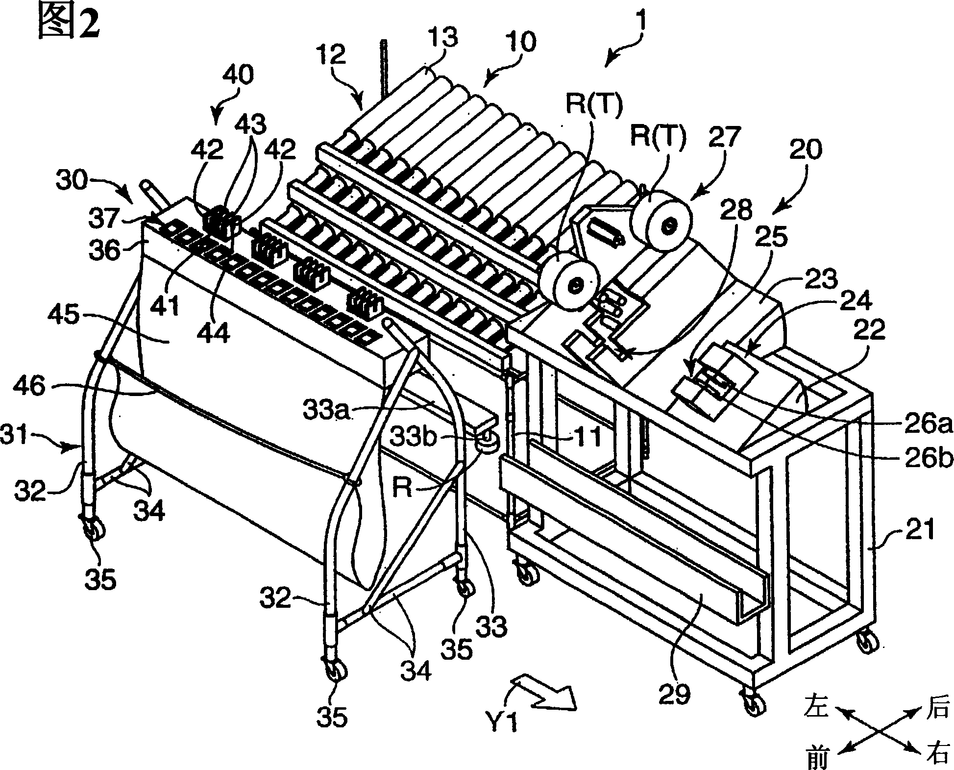
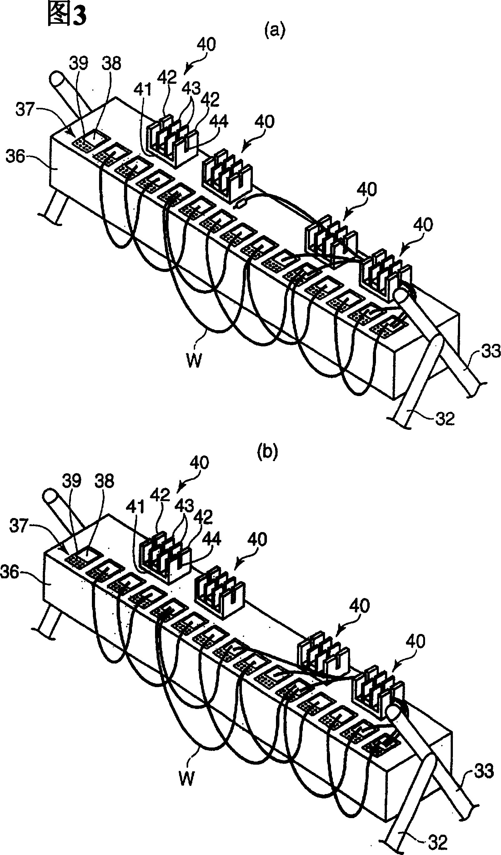

Image

  • Line pencil manufacturing method and manufacturing device
  • Line pencil manufacturing method and manufacturing device
  • Line pencil manufacturing method and manufacturing device

Examples


Embodiment Construction

[0034] Preferred embodiments of the present invention will be described below with reference to the drawings.

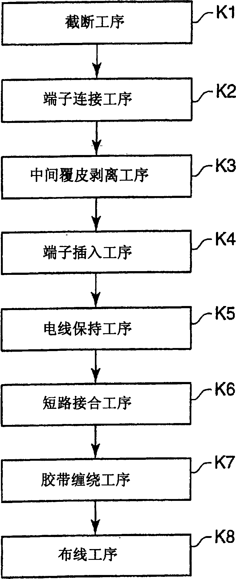
[0035] figure 1 It is a flowchart showing the outline of the manufacturing process of the wire harness according to the embodiment of the present invention.

[0036]refer to figure 1 , when manufacturing the wire harness, the wire harness undergoes the following processes: first, the cutting process K1 is used to measure and cut off the covered wire; and the terminal connection process K2 is used to connect the crimped terminal and the like to the cut off covered wire. That is, in these steps, the covered electric wire is cut to a predetermined length, and the coverings at both ends of the cut covered electric wires are peeled off, and then the crimp terminals and the like are bonded to the parts peeled off from these coverings. At least one end of the exposed core wire is connected. The operations of the cutting step K1 and the terminal connecting step K2 can b...


PUM


Abstract

Provided is a manufacturing method and a manufacturing device for wire harness capable of improving the workability and reducing the cost. The manufacturing method of wire harness is provided with a cutting process K1 adjusting the length of covered wire and cutting it, a terminal connection process K2 connecting a terminal to at least one end part of the covered wire after cutting, a terminal insertion process K4 holding a housing of a connector on a working table, and inserting the corresponding terminal of the covered wire into the housing, a wire holding process K5 holding the middle part of a covered wire out of connected covered wires being connected, to which a short-circuit bonding is to be applied while superposing it on a wire holding part on the working table, a short-circuit connection process K6 short-circuiting the middle part of the covered wire being held, and a wiring process K8 moving the connection body of the covered wire processed at the process K7 from the working table onto a drawing board and wiring it.

Description

technical field [0001] The present invention relates to a wire harness manufacturing method for manufacturing a wire harness by connecting a terminal connected to a terminal of a plurality of covered electric wires with a connector housing, and short-circuit bonding with a specific covered electric wire and manufacturing device. Background technique [0002] A wire harness is an electrical wiring system in which a plurality of connectors and a plurality of wires connected to these connectors form a prescribed circuit network. [0003] When manufacturing the above-mentioned wire harness, there are the following processes: a cutting process, which is used to measure and cut off the covered wire; a terminal connection process, which connects the terminal to the cut covered wire; and a terminal insertion process, which inserts the terminal connected to the covered wire. Connector sheath; and the wiring process of wiring the covered wire after the terminal is inserted on the dra...

Claims


Application Information

Patent Timeline
IPC IPC(8): H01R43/00H01B13/00H01B13/012H01R43/01H01R43/20H02G1/14
Inventor 青井觉
Owner SUMITOMO WIRING SYST LTD
Learn More