
Power tool

A power tool, reciprocating motion technology, applied in striking tools, manufacturing tools, lightweight impact tools, etc., can solve the problems of complex structure and assembly operations, increase the weight of the electric hammer, damage the appearance of the electric hammer, etc.

Active Publication Date: 2004-12-01
MAKITA CORP
View PDF0 Cites 3 Cited by
  • Summary
  • Abstract
  • Description
  • Claims
  • Application Information

AI Technical Summary

Problems solved by technology

Therefore, construction and assembly operations are complicated, and the weight of the entire electric hammer is increased
In addition, since the space for accommodating the dynamic shock absorber is secured, the appearance of the rotary hammer is compromised

Method used


Image

  • Power tool
  • Power tool
  • Power tool

Examples


Embodiment Construction

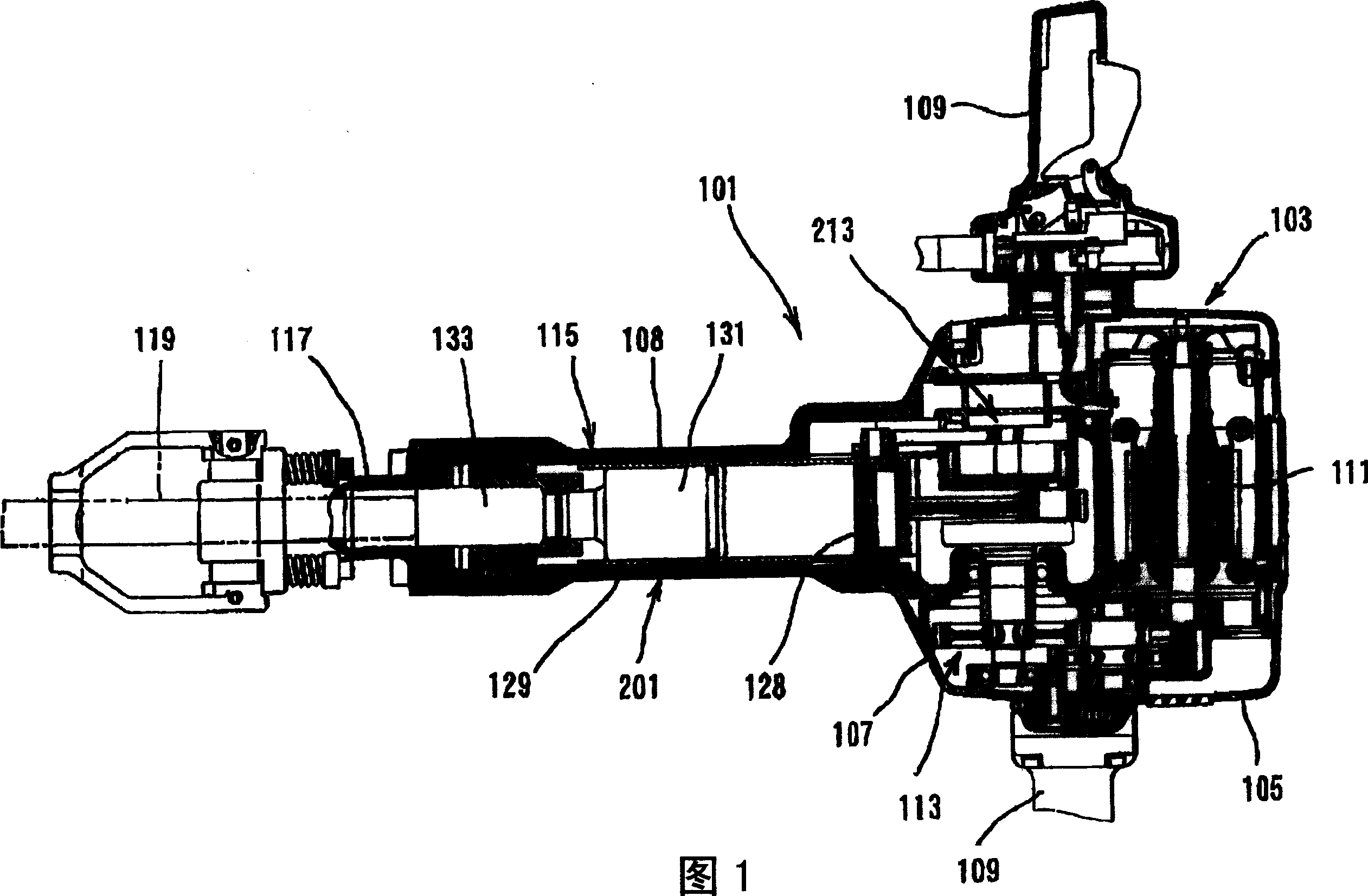
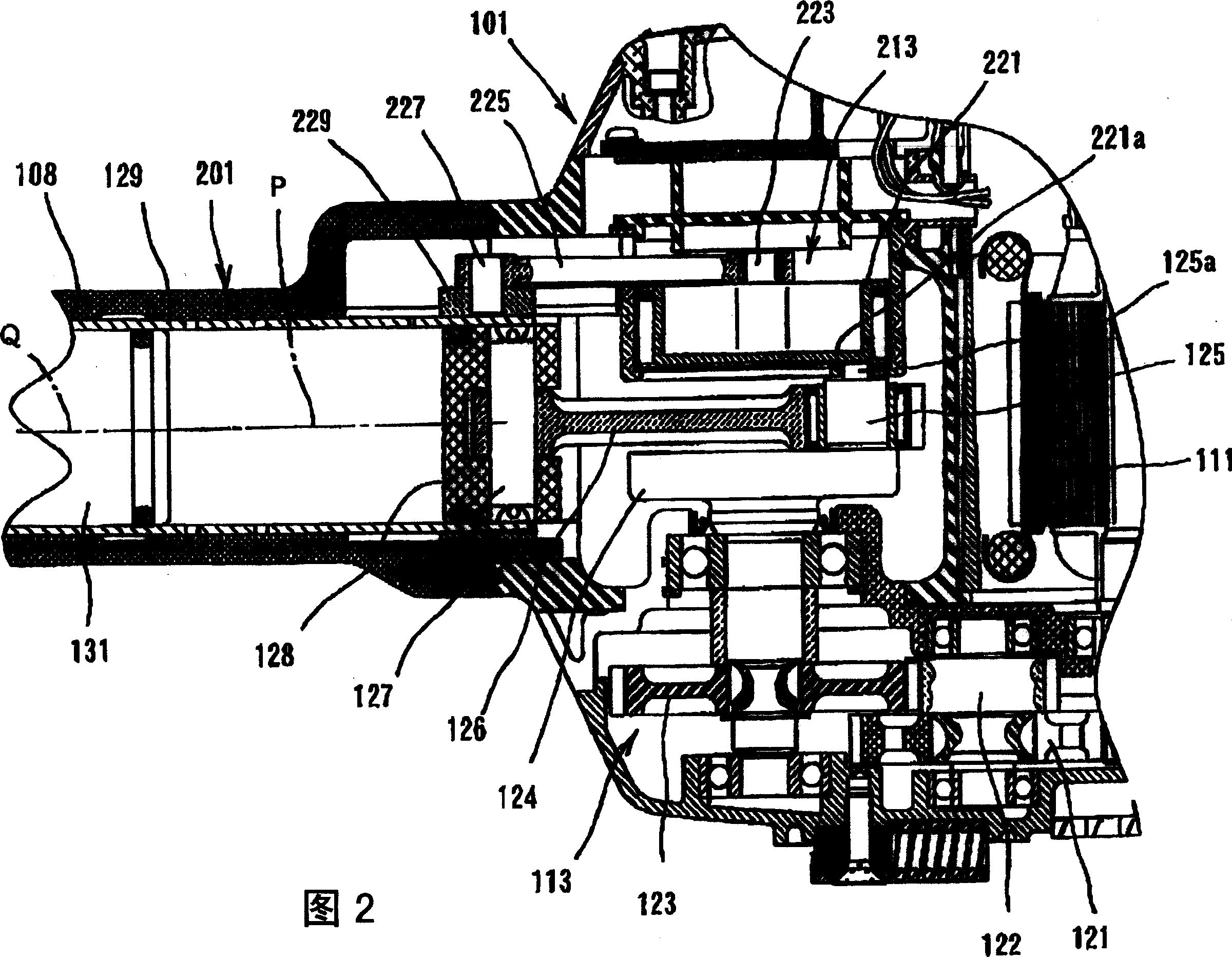
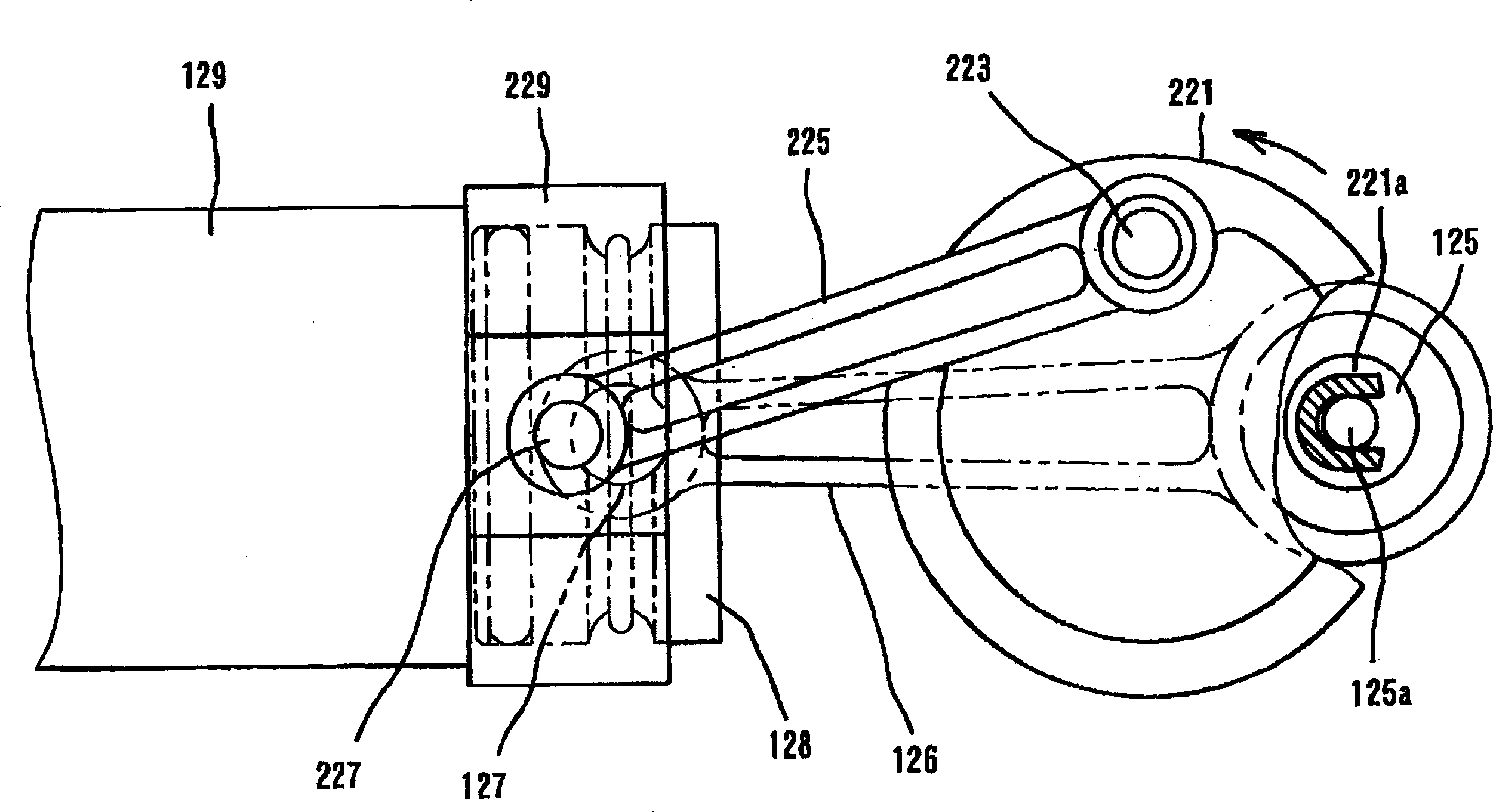
[0028] According to the present invention, a representative power tool includes: a hammer, a bit and a shock absorber. The hammer reciprocates under the action of air pressure fluctuations in the cylinder. The hammer can directly strike the cutter head under the action of the air pressure fluctuation in the cylinder. Alternatively, the air pressure fluctuations in the cylinder drive the hammer to hit another impact force transmission element such as an impact bolt, and then the impact force transmission element impacts the cutter head. The cutting head performs a predetermined operation under the impact force of the hammer. The shock absorber reduces shock on the ram by reciprocating in a direction opposite to that of the ram. The trajectory of the center of gravity of the shock absorber is designed to coincide with the trajectory of the center of gravity of the hammer. With this configuration, since no rotational (turning) moment is applied to the reciprocating cylinder du...


PUM


Abstract

It is an object of the invention to provide a technique for further improving the vibration reducing performance in the power tool, while avoiding complicating the construction of the power tool. According to the present invention, a representative power tool may comprise a striker, a tool bit and a vibration reducer. The vibration reducer serves to reduce vibration on the striker by reciprocating in a direction opposite to the reciprocating direction of the striker. The path of the center of gravity of the vibration reducer is arranged to coincide with a path of the center of gravity of the striker. With such construction, because rotating moment is not exerted onto the reciprocating cylinder during the operation of the power tool, vibration reduction can be performed in a stable manner.

Description

technical field [0001] The present invention relates to an electric tool, in particular to a technology for reducing and alleviating vibrations in electric tools such as electric hammers and hammer drills. Background technique [0002] Japanese Unexamined Patent Publication No. 52-109673 discloses an electric hammer with a shock absorbing device. The known rotary hammer comprises a vibration-insulating chamber arranged in the lower area of ​​the rotary hammer housing. A dynamic shock absorber is arranged in the vibration isolation chamber to reduce and alleviate the strong vibration along the axial direction of the electric hammer during operation. [0003] However, the vibration isolation chamber is formed separately within the casing, in which the components of the shock absorber are integrated. Therefore, construction and assembly operations are complicated, and the weight of the entire electric hammer is increased. In addition, since a space for accommodating the dyna...

Claims


Application Information

Patent Timeline
Patent Type & Authority Applications(China)
IPC IPC(8): B25D11/12B25D17/24
CPCB25D11/125B25D17/24B25D2217/0088
Inventor 生田洋规荒川琢雄川上高弘
Owner MAKITA CORP
Learn More