
Multifunctional high power machine for earthworker's cloth testing and use thereof

A geotextile and multi-functional technology, applied in the direction of applying stable tension/compression to test the strength of materials, can solve the problems of uneven stress on geotextiles, affecting test results, laborious and laborious, etc., and achieve a wide range of test items and testing Accurate data and high efficiency

Inactive Publication Date: 2004-11-03
WATER RESOURCES RES INST OF SHANDONG PROVINCE
View PDF0 Cites 15 Cited by
  • Summary
  • Abstract
  • Description
  • Claims
  • Application Information

AI Technical Summary

Problems solved by technology

Although the existing test equipment can complete the test work, it is necessary to replace the entire assembly of the measuring head for each test item. Moreover, the device for clamping the geotextile is realized by tightening the bolts, which is laborious and laborious. And the force of the geotextile is not uniform, which affects the test results
In addition, for the test items of rigid foam and soft foam boards, that is, the test of pressure strength and fracture test, when changing the test items, it is necessary to replace a whole set of components, which is time-consuming, laborious and costly.

Method used

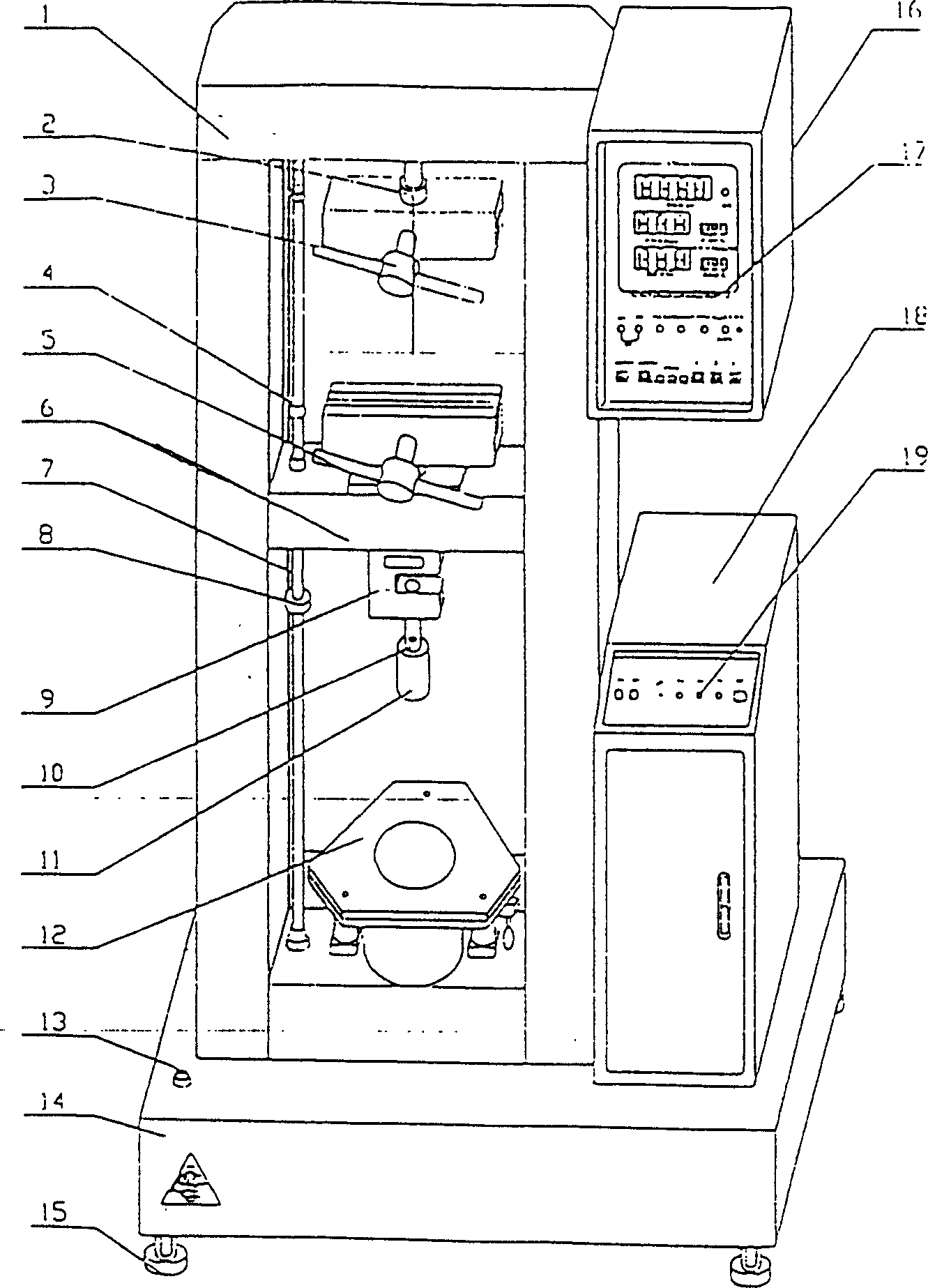

Image

  • Multifunctional high power machine for earthworker's cloth testing and use thereof
  • Multifunctional high power machine for earthworker's cloth testing and use thereof
  • Multifunctional high power machine for earthworker's cloth testing and use thereof

Examples


Embodiment 1

[0046] Example 1: Structure as figure 1 , 2 , 10, it is composed of beam 6, power part, lifting clamping device 12, CBR bursting probe 22, probe base 10, sensor 9, microcomputer control device 16, display device 17, door frame 1 and base 23 Among them, the base 23 is provided with four adjustable feet 15, the clamping device 12 is in the door frame 1, the upper part of the inner side of the door frame 1 is connected to the upper clamp 3 through the upper connecting shaft 2 to stretch and tear, and stretch The tearing lower gripper 5 is set on the upper part of the beam 6, the two ends of the beam 6 are connected to the power part, the beam 6 can move up and down in the mast 1, the lower part of the beam 6 is provided with a 30KN sensor 9, and a measuring device is connected below. Head seat 10. The lifting clamping device 12 is clamped by the pneumatic part. The lifting clamping device 12 is composed of a lower fixed part, an upper movable part, a cylinder and a valve. The lower ...

Embodiment 2

[0048] Example 2: Structure as image 3 As shown, when the ball burst test is performed, a 3KN sensor 11 is connected with a pin on the probe base 10. The lower end of the 3KN sensor 11 has a connecting wire hole, and the ball burst probe 20 is connected to the 3KN sensor 11 through a thread In the connecting wire hole, the other structure and work are the same as in Example 1.

Embodiment 3

[0049] Example 3: Structure as Figure 4 As shown, when doing a puncture test, connect a 3KN sensor 11 with a pin on the probe base 10. The lower end of the 3KN sensor 11 has a connecting wire hole, and the puncture probe 21 is connected to the connecting wire hole of the 3KN sensor 11 through a thread Inside, the other structure and work are the same as the first embodiment.


PUM


Abstract

The present invention relates to material test machine technology and is one geotextile strength test machine and its application. The test machine includes crossbeam, driving mechanism, test head, sensor module, microcomputerized controller, display, portal and pedestal. The upper holder for testing tensile strength and tear strength is set on the portal, and the lower holder is set on the crossbeam. The crossbeam with ends connected to the driving mechanism may be shifted inside the portal, and the test head and the sensor module are set on the crossbeam and connected together. There is elevated clamping unit set on the pedestal. The test head may be one of the CBR bursting test head, spherical bursting test head, piercing test head, plate material pressing test head and plate material breaking test head. The present invention may be used in complete various test jobs.

Description

(1) Technical field [0001] The invention relates to a geotextile strength machine and its application, and belongs to the technical field of material testing machines. (2) Background technology [0002] The shortage of water resources has become a major problem restricting economic development. People have adopted various measures to save water resources. Among them, the application of geosynthetics is an ideal method. In flood relief projects, the use of geosynthetics is very large. In order to make full use of the geosynthetic fabric, it is required to test the performance of the geosynthetic fabric, which gives people a new subject. Although the existing test equipment can complete the test work, each time a project is tested, the entire assembly of the probe must be replaced. Moreover, the device for clamping the geotextile is realized by tightening the bolts, which is laborious and laborious. In addition, the uneven force of the geotextile affects the test results. In additi...

Claims


Application Information

Patent Timeline
IPC IPC(8): G01N3/10
Inventor 宫爱华于方明张广贞冯质刚陶尊丽鲁学恩
Owner WATER RESOURCES RES INST OF SHANDONG PROVINCE
Learn More