
Intelligent railway signal power source switching module

A technology of power switching and railway signaling, which is applied in the direction of emergency power supply arrangements, electrical components, circuit devices, etc., and can solve problems such as contact bonding, interference with driving order, and power failure accidents at signal points

Inactive Publication Date: 2004-10-06
宁波宝鑫铁路信号设备制造有限公司 +1
View PDF1 Cites 4 Cited by
  • Summary
  • Abstract
  • Description
  • Claims
  • Application Information

AI Technical Summary

Problems solved by technology

[0002] The intelligent power supply panel for the centralized power supply of Railway Electric is used to provide AC and DC power supplies for signal flashing power supply, track circuit, electric switch machine, centralized dispatching, microcomputer interlocking, relays, consoles and display panels, in order to ensure railway transportation Safety, the external grid power supply must be powered by two power sources, so it is necessary to have a two-way power switching device, which is used to switch to another power supply in a very short time when one power supply fails or when a certain power supply is routinely overhauled To ensure the normal power supply of the smart power panel, the standard switching time established by the Ministry of Railways is 150ms, and the ideal state should be zero-time switching; most of the existing two-way power switching is achieved by mechanical contactors. On the one hand, it is difficult for the contactor to achieve switching with a switching time of less than 40ms. On the other hand, because of the frequent occurrence of failures such as coil burnout, contact bonding, and mechanical jamming during operation, the power failure accident at the signal point has seriously interfered with the normal operation. Driving order; for solving the above problems, China's utility model patent discloses a "dual-way power supply automatic switching solid-state controller" (patent number: 02204997.5), which consists of main road and backup road input circuit, rectification absorption circuit, DC excitation circuit, Composed of a controlled power switch circuit and a switching control circuit, the switching time is 20-30ms. Although it can meet the requirements of the Ministry of Railways for a switching time of less than 150ms, there is still a big gap with the ideal zero-time switching

Method used


Image

  • Intelligent railway signal power source switching module
  • Intelligent railway signal power source switching module
  • Intelligent railway signal power source switching module

Examples


Embodiment Construction

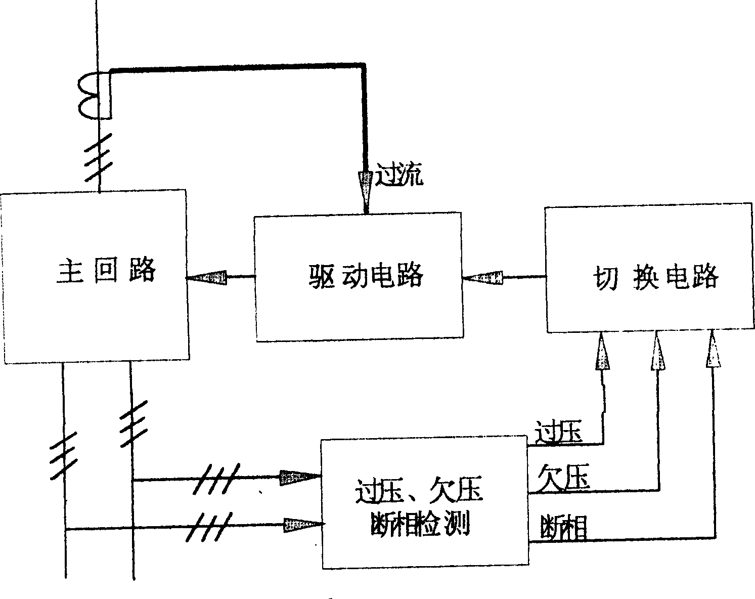
[0012] refer to figure 1 , a kind of intelligent railway signal power switch module of the present invention, mainly is made up of: 1) main circuit, 2) overvoltage, undervoltage and open-phase detection circuit, 3) switching circuit, and 4) driving circuit four parts;

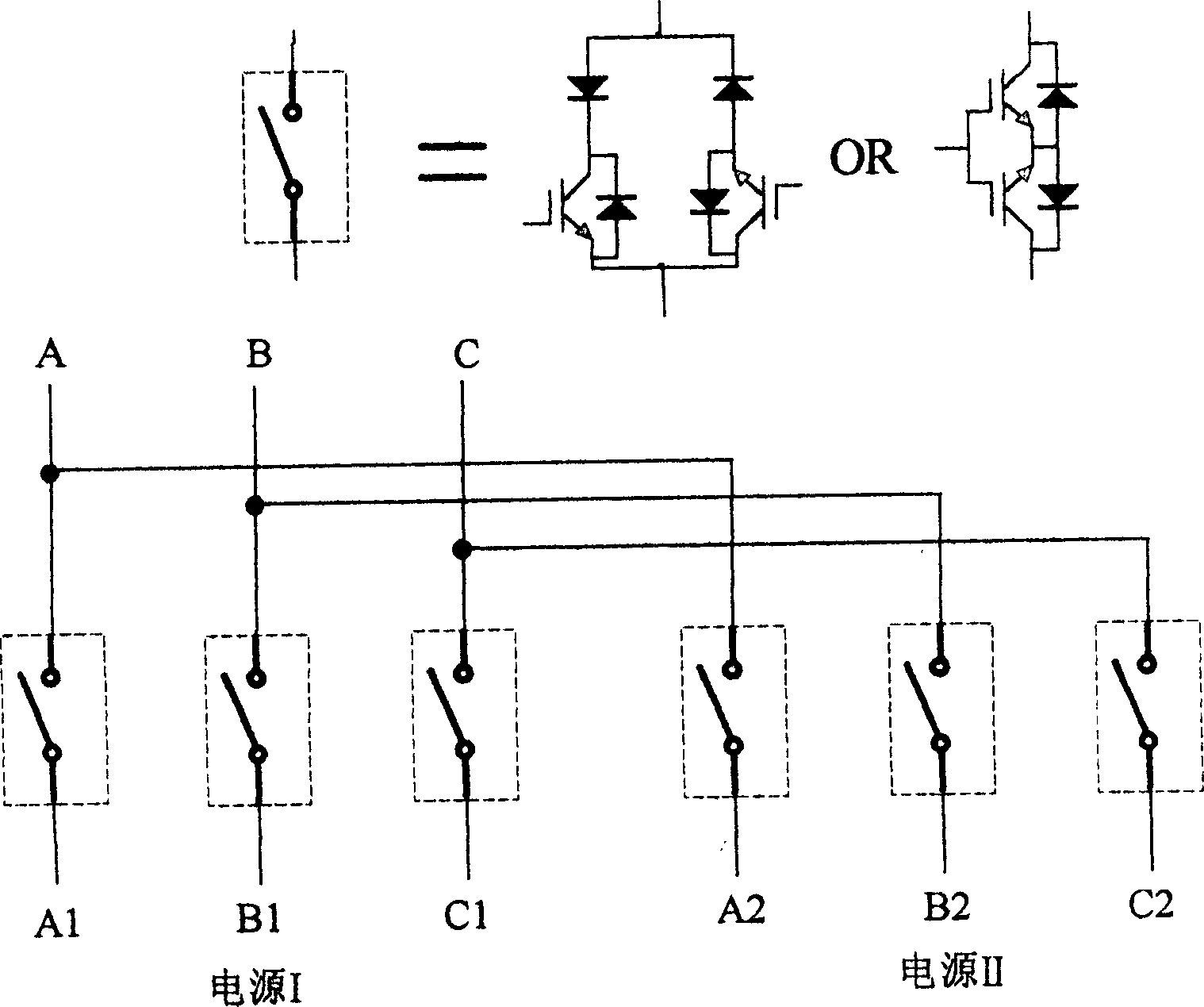
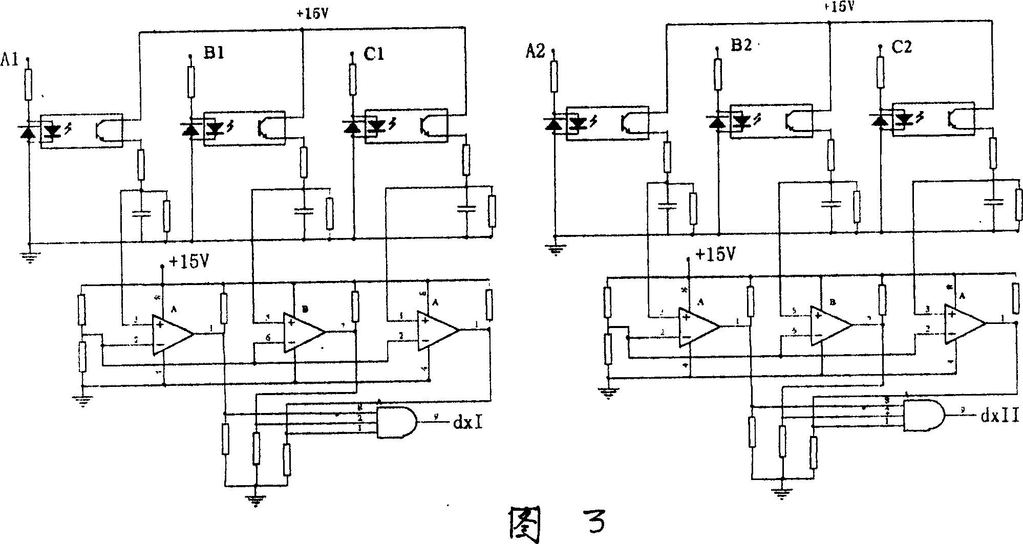
[0013] refer to figure 2 As shown in Figure 4, the main circuit is composed of two input power sources, that is, power supply I (three-phase A1, B1, C1) and power supply II (three-phase A2, B2, C2), composed of series or parallel IGBT tubes The switching circuit, the output is three-phase A, B, C; the overvoltage, undervoltage and phase failure detection circuit is composed of resistors, optocoupler devices, and follow-up circuits, which respectively monitor the voltages and The input current is sampled by a linear optocoupler and other devices, connected to a comparator, and connected to a NOR gate after amplification to control the IGBT tube; the switching circuit is connected to overvoltage, undervoltage a...


PUM


Abstract

An intelligent power supply switching module for the railway signalling can automatically perform the switching between two power supplys when the undervoltage, overvoltage, or phase lost occurs. It is composed of primary circuit, the overvoltage, undervoltage and phase lost detector, switching circuit and drive circuit. Its primary circuit has two input power supplys and a switch circuit consisting of serially or parallelly connected two IGBTs for output. Its advantages are high detecting and switching speed (less than 2 ms).

Description

technical field [0001] The invention relates to the technical field of railway traffic management and guaranteeing railway traffic safety, in particular to the technical field of automatic switching of railway signal dual-way power supplies. Background technique [0002] The intelligent power supply panel for the centralized power supply of Railway Electric is used to provide AC and DC power supplies for signal flashing power supply, track circuit, electric switch machine, centralized dispatching, microcomputer interlocking, relays, consoles and display panels, in order to ensure railway transportation Safety, the external grid power supply must be powered by two power sources, so it is necessary to have a two-way power switching device, which is used to switch to another power supply in a very short time when one power supply fails or when a certain power supply is routinely overhauled To ensure the normal power supply of the smart power panel, the standard switching time e...

Claims


Application Information

Patent Timeline
Patent Type & Authority Applications(China)
IPC IPC(8): H02J3/00H02J9/06
Inventor 刘小宁陆文光
Owner 宁波宝鑫铁路信号设备制造有限公司
Learn More