
Liquid crystal display device and its driving method

A technology of a liquid crystal display device and a driving method, which is applied to static indicators, instruments, condensed water discharge, etc., and can solve problems such as insufficient suppression of flickering, high switching frequency of common electrode potential, etc.

Inactive Publication Date: 2004-09-29
SHARP KK
View PDF1 Cites 33 Cited by
  • Summary
  • Abstract
  • Description
  • Claims
  • Application Information

AI Technical Summary

Problems solved by technology

However, when the line inversion driving method is used instead of the frame inversion driving method, the frequency of polarity inversion (inversion frequency) in the video signal that should be applied to the liquid crystal panel becomes higher, and in order to reduce the driving IC (integrated Circuit) necessary withstand voltage, the potential switching frequency of the common electrode also becomes higher, resulting in increased power consumption
In addition, flicker cannot be sufficiently suppressed only by the row inversion driving method.

Method used


Image

  • Liquid crystal display device and its driving method
  • Liquid crystal display device and its driving method
  • Liquid crystal display device and its driving method

Examples


Embodiment Construction

[0056] Embodiments of the present invention will be described below with reference to the drawings.

[0057] 1. The first embodiment

[0058] 1.1. Overall composition and action

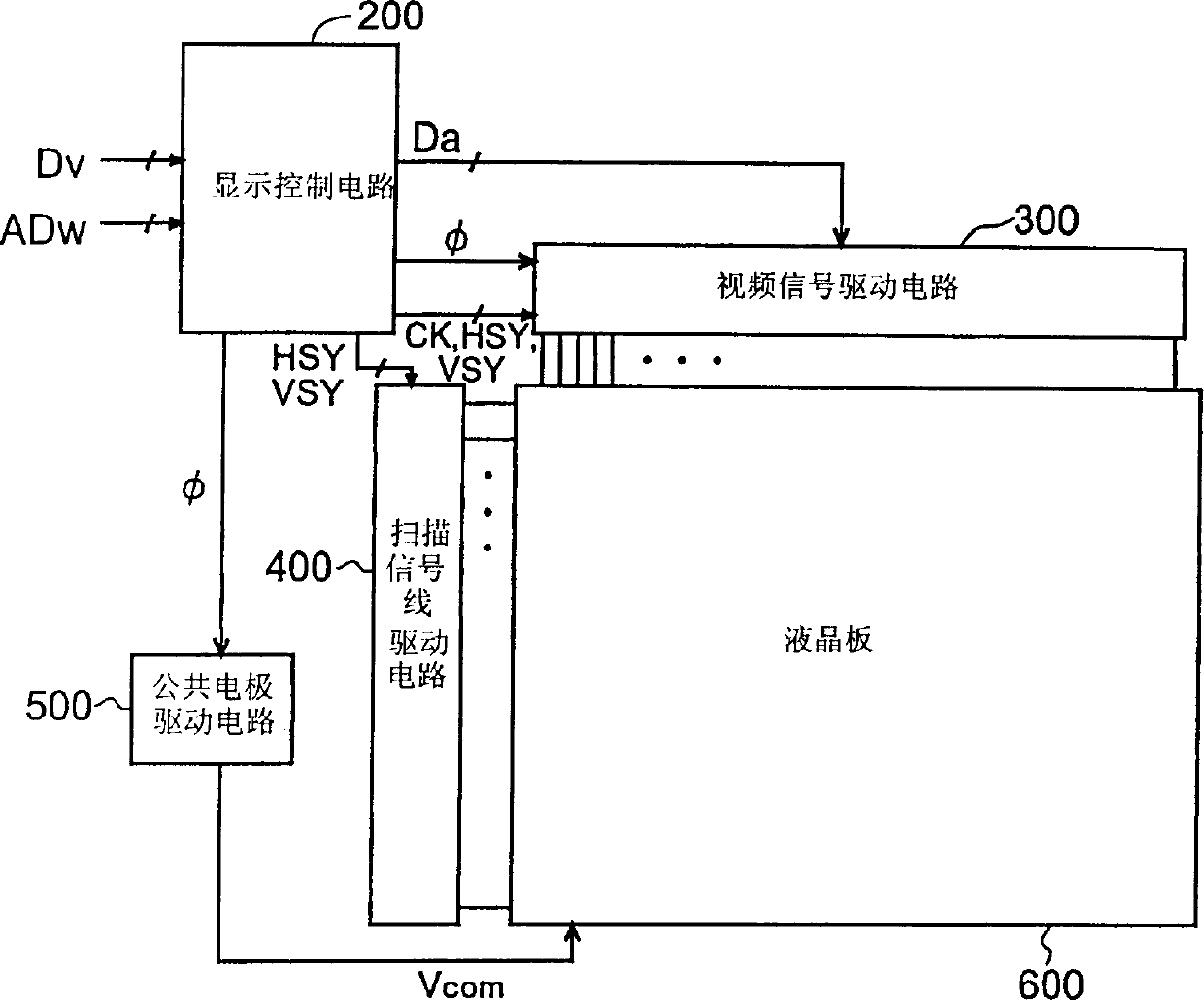
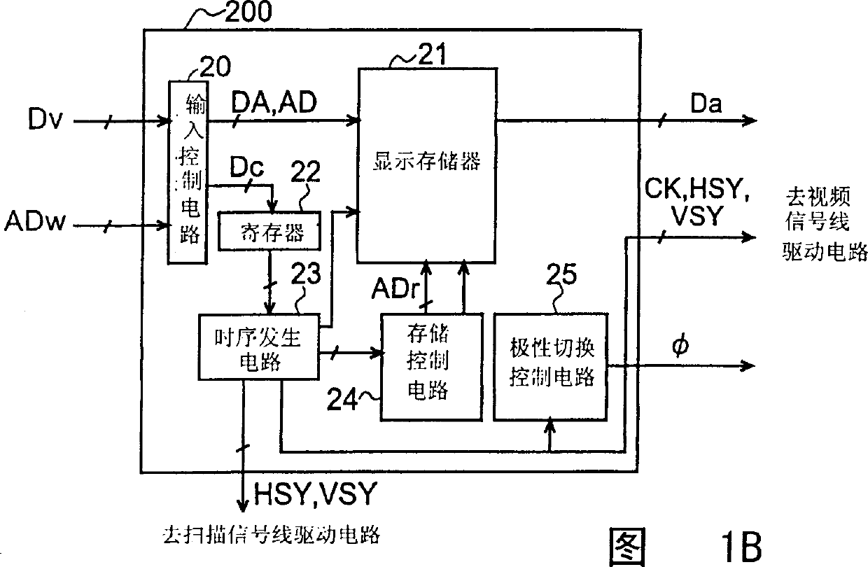
[0059] FIG. 1A is a block diagram showing the configuration of a liquid crystal display device according to a first embodiment of the present invention. The liquid crystal display device includes a display control circuit 200, a video signal line drive circuit 300 (also called a "column electrode drive circuit" or a "data line drive circuit"), a scanning signal line drive circuit (also called a "row electrode drive circuit") Or “gate line driving circuit) 400 , common electrode driving circuit 500 and active matrix liquid crystal panel 600 .

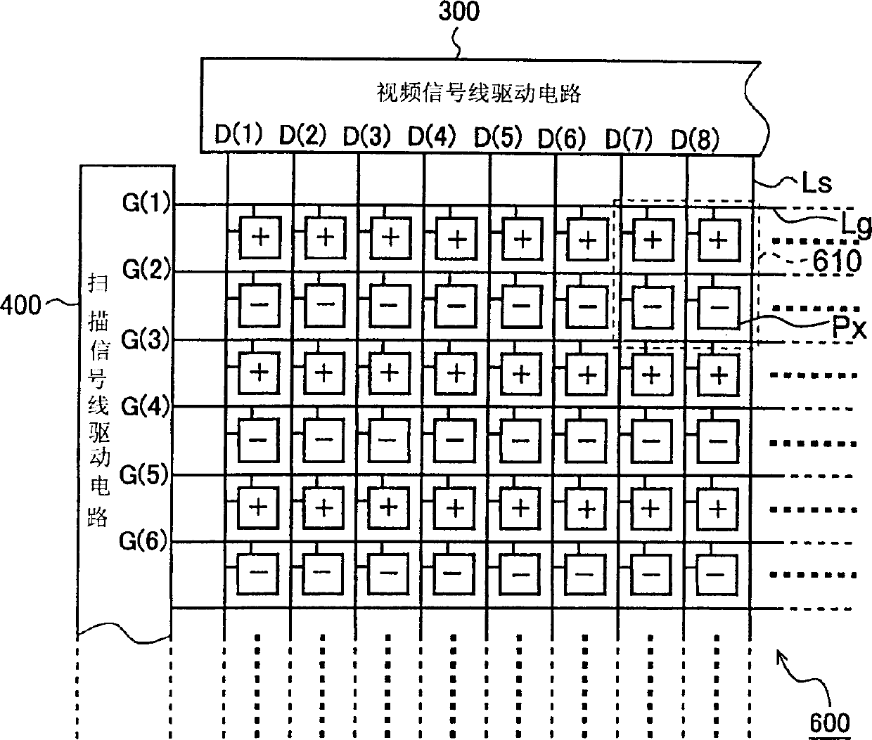
[0060] The liquid crystal panel 600 as a display unit in this liquid crystal display device includes a plurality of scanning signal lines (row electrodes) respectively corresponding to horizontal scanning lines in an image represented by image data Dv receive...


PUM


Abstract

In a liquid crystal display device, a first skipping scanning process is performed by activating the scanning signals G(1), G(3) and G(5) corresponding to the odd-numbered rows in a pixel matrix made of numerous pixel formation portions in that order in a first half-period of a given frame, and voltages corresponding to the pixel values to be written into the pixel formation portions of the odd-numbered rows of the pixel matrix are applied to the video signal lines as positive-polarity video signals. In a second half-period of that frame, a second skipping scanning process is performed by activating the scanning signals G(2), G(4) and G(6) corresponding to the even-numbered rows in the pixel matrix in that order, and voltages corresponding to the pixel values to be written into the pixel formation portions of the even-numbered rows of the pixel matrix are applied to the video signal lines as negative-polarity video signals. Thus, line inversion driving is accomplished.

Description

technical field [0001] The present invention relates to a liquid crystal display device and a driving method thereof, and more specifically relates to AC driving in an active matrix type liquid crystal display device. Background technique [0002] In order to suppress liquid crystal degradation and maintain display quality in liquid crystal display devices, AC drive is generally performed. However, in an active liquid crystal display device, since the characteristics of switching elements such as TFTs (thin film transistors) provided in each pixel are not perfect, even if the video signal from the video signal line (column electrode) of the liquid crystal panel is applied with a voltage The positive and negative of the video signal output by the line drive circuit (also called "column electrode drive circuit" or "data line drive circuit"), that is, the positive and negative of the applied voltage based on the potential of the common electrode is symmetrical, and the transmis...

Claims


Application Information

Patent Timeline
Patent Type & Authority Applications(China)
IPC IPC(8): G02F1/133G09G3/20G09G3/36
CPCG09G2320/0247G09G2300/0809G09G2330/021G09G2310/0224G09G3/3614E06B3/4609E06B3/301E06B7/14E06B7/2307E05Y2800/428
Inventor 大和朝日中野武俊柳俊洋
Owner SHARP KK
Learn More