Internal balance hold-down filler
A technology of filling device and internal balance, which is applied in the field of molecular sieve compacting device in the gas separation cylinder of nitrogen and oxygen generators, which can solve the problems of equipment space limitation and large addition, and achieve the effect of reducing the service life
- Summary
- Abstract
- Description
- Claims
- Application Information
AI Technical Summary
Problems solved by technology
Method used
Image
Examples
Embodiment 1
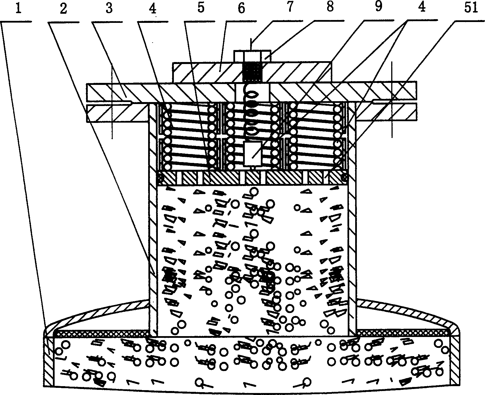
[0017] Example 1 as figure 1 As shown, in this example, the internal balance compression filling device is provided with a sleeve body 2 connected with the gas separation device 1, a piston 5 is arranged in the sleeve body 2, and a top cover 3 is connected on the sleeve body 2, and the top cover 3 is connected with the A compression spring 4 and an extended distance disengagement switch 9 that can contact / leave with the piston 5 are arranged between the pistons 5, and the extension distance disengagement type switch 9 is electrically connected with the alarm device of the peripheral device through the wire 7. A through hole 51 is provided on the piston 5, a cover 6 is provided on the top cover, and a nut 8 is provided on the cover.
Embodiment 2
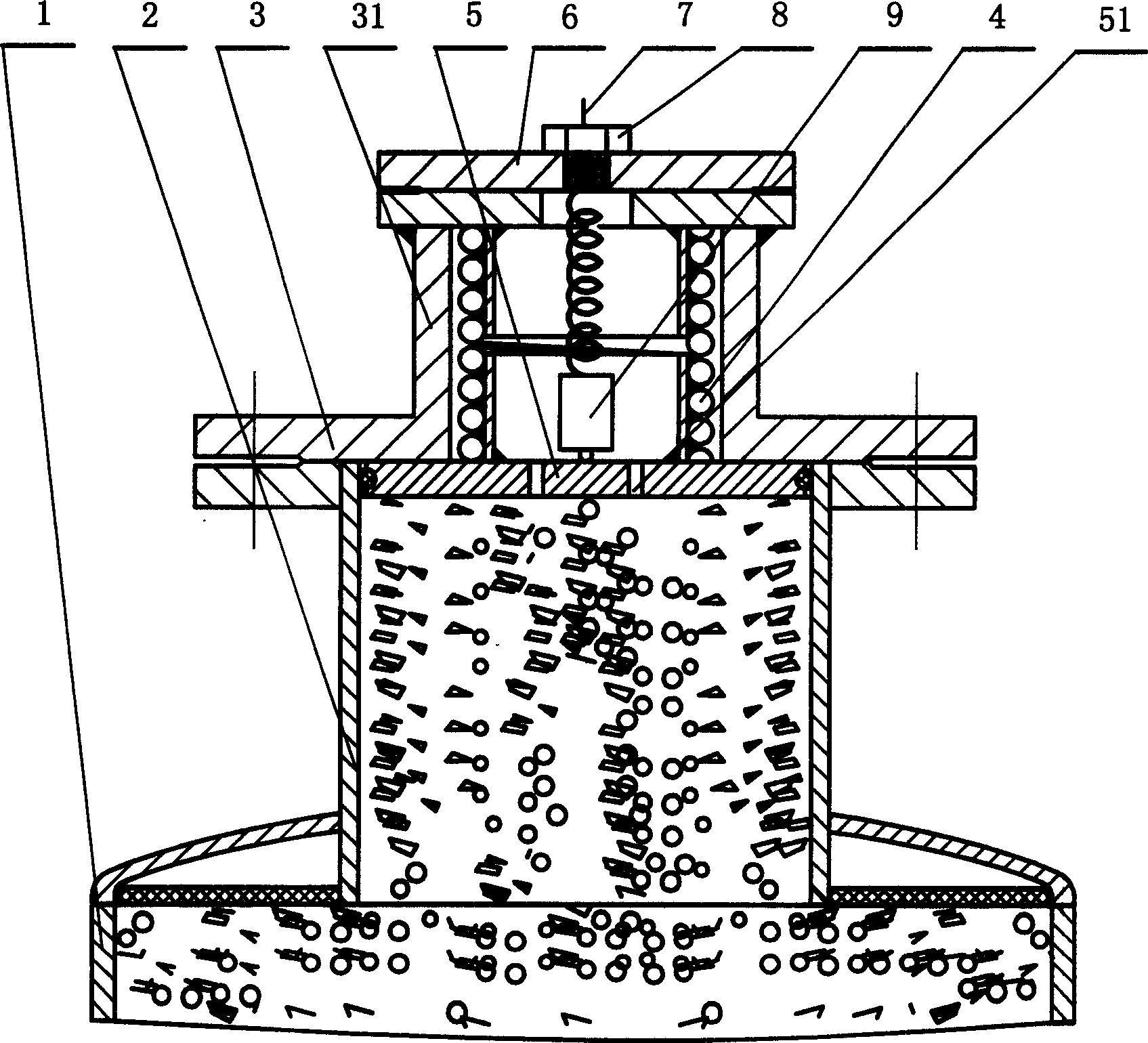
[0018] Example 2 as figure 2 As shown, the internally balanced compression filling device in this example is different from the previous example in that the top cover 3 is provided with an axially outwardly protruding cavity shell 31, and the compression spring 4 and the extended-range disengagement switch 9 are located in the Inside the cavity shell 31. Other structures are the same as the above example.
Embodiment 3
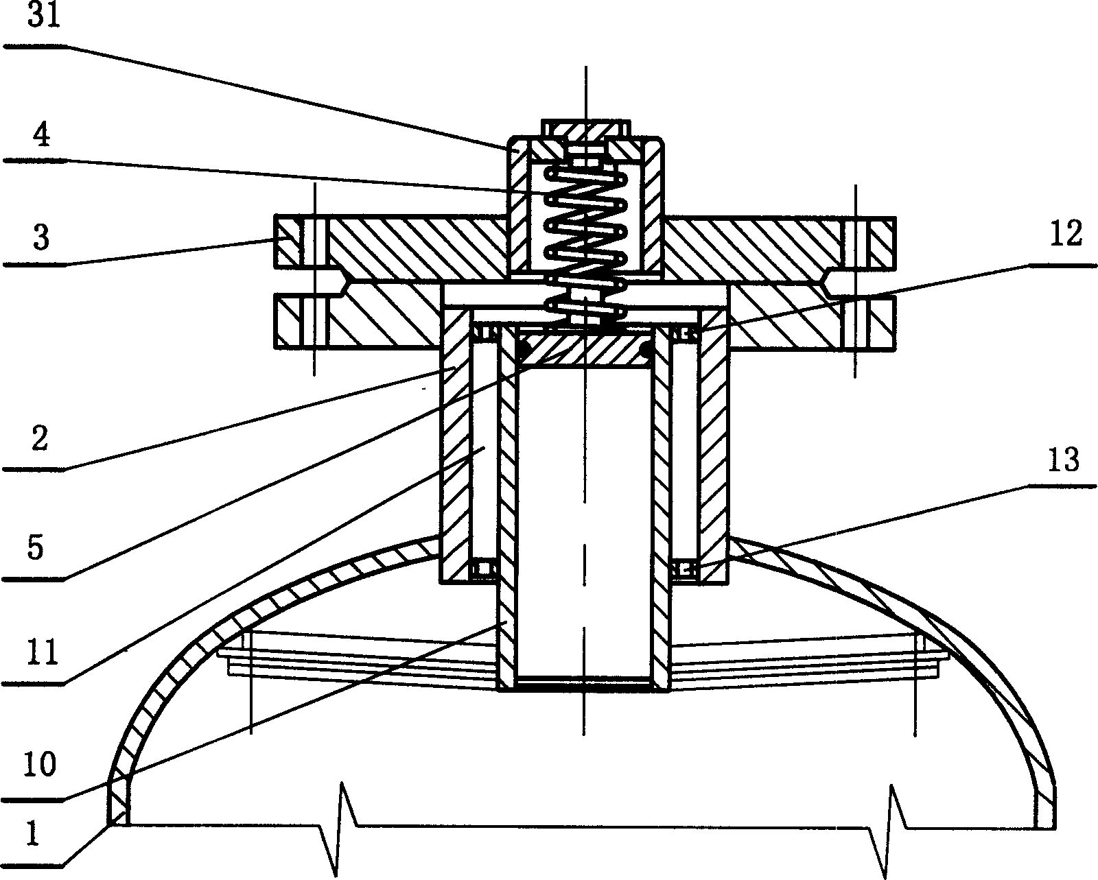
[0019] Example 3 as image 3 As shown, the inner balanced compression filling device in this example is different from Example 2 in that an inner sleeve 10 is provided in the sleeve body 2, a piston 5 is arranged in the inner sleeve 10, and there is a gap between the outer wall of the inner sleeve 10 and the inner wall of the sleeve body 2 Between the chamber 11, the upper and lower parts of the chamber 11 are respectively provided with an upper cover and a lower cover located between the outer wall of the inner sleeve 10 and the inner wall of the sleeve body 2, and the upper and lower covers are respectively provided with a pressure balance hole I12 and a pressure balance Hole II13.
PUM
 Abstract
Description
Claims
Application Information
 - R&D
- Intellectual Property
- Life Sciences
- Materials
- Tech Scout
- Unparalleled Data Quality
- Higher Quality Content
- 60% Fewer Hallucinations
Browse by: Latest US Patents, China's latest patents, Technical Efficacy Thesaurus, Application Domain, Technology Topic, Popular Technical Reports.
© 2025 PatSnap. All rights reserved.Legal|Privacy policy|Modern Slavery Act Transparency Statement|Sitemap|About US| Contact US: help@patsnap.com


