
Steam turbine and its rotor and method for active colling the same rotor and application of the same method

A steam turbine rotor, active cooling technology, applied in the direction of machine/engine, engine starting, stator, etc., can solve problems such as increased rotor temperature and harmful heat load

Inactive Publication Date: 2004-09-08
SIEMENS AG
View PDF3 Cites 4 Cited by
  • Summary
  • Abstract
  • Description
  • Claims
  • Application Information

AI Technical Summary

Problems solved by technology

The problem here is that, when using the previously used turbine materials, the greater load on the rotor due to the higher steam parameters leads to a harmful thermal load on the rotor and thus to impermissible changes in the rotor temperature. increase

Method used


Image

  • Steam turbine and its rotor and method for active colling the same rotor and application of the same method
  • Steam turbine and its rotor and method for active colling the same rotor and application of the same method
  • Steam turbine and its rotor and method for active colling the same rotor and application of the same method

Examples


Embodiment Construction

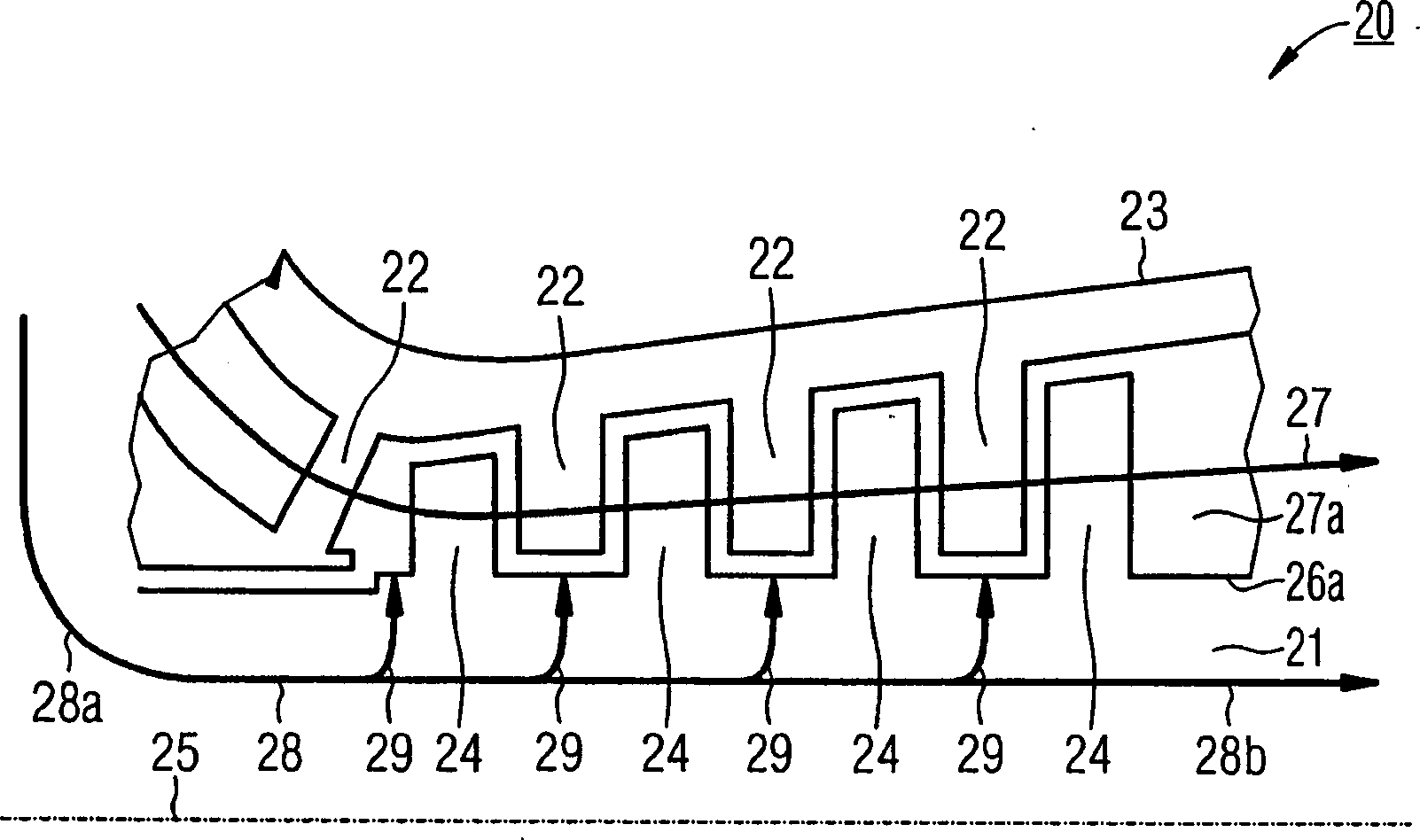
[0051] Currently known steam turbine rotors are basically made as integral rotors and have no active cooling system at all. But in the prior art according to US 6102654, such as figure 1 As shown, a steam turbine 1 is presented which has an active cooling system limited to cooling the inflow region. The steam turbine has a rotor 3 mounted rotatably on a shaft 2 on which a number of rotor blades 4 are mounted. They are arranged in a fixed housing 5 provided with guide vanes 6 . The rotor 3 is moved by means of the rotor blades 4 by the working fluid 8 flowing into the inflow region 7 . In addition to the working medium 8 , the coolant 10 flows into the working medium 8 through a separate inlet region 9 . During this process, the coolant 10 cools only the fixed first guide vane ring 11 and the shielding plate 12 through the inflow. This reduces the thermal load on the rotor 3 and the first guide vane ring 11 . Furthermore, the cooling fluid 10 is directed from the inlet reg...


PUM


Abstract

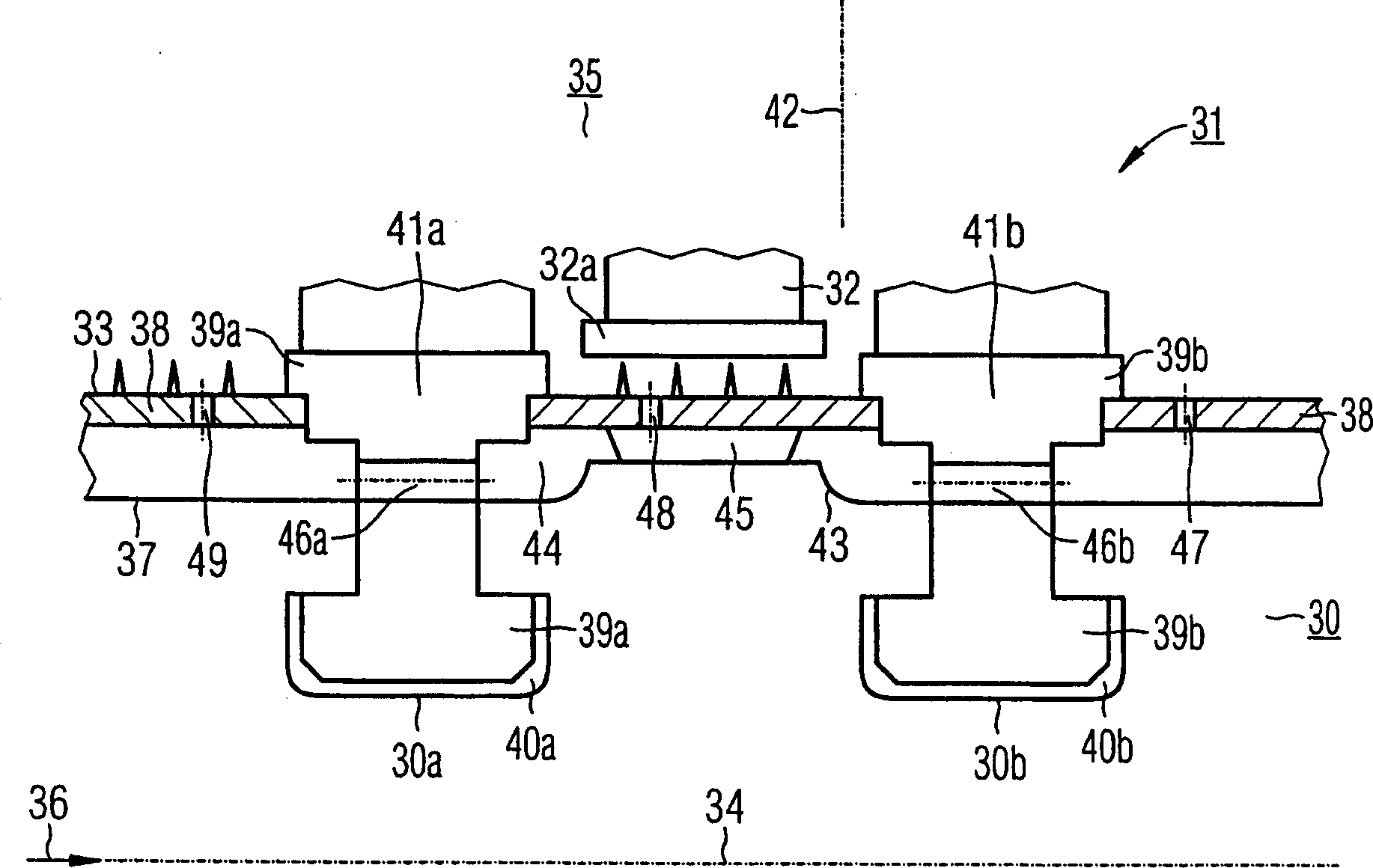
An axially-extended vapor turbine rotor (31) comprises an outer boundary enclosing a space (35) receiving the main flow (36) of the fluid working medium with an external position (30a) holding a first blade (41a). An integrated channel (46a,b) extends between a region before the first position (30a) and a second region (30b). An Independent claim is also included for an active cooling process for the turbine above.

Description

technical field [0001] The present invention relates to a steam turbine rotor extending axially and having: an outer side defining an outer cavity for accommodating a main flow of a working fluid; and a first location along the outer side, The first vane set is fixed in this position. The invention also relates to a steam turbine. Furthermore, the invention also relates to a method for actively cooling a rotor of a steam turbine of the type described. Background technique [0002] In order to increase the achievable steam temperature when charging the steam turbine with hot steam, efforts are made to cool the components subjected to high loads in a targeted manner. This includes implementing thermal shielding (if possible) and dissipating heat through a correspondingly designed cooling unit. Within the scope of this application, a steam turbine is understood as meaning any turbine or sub-turbine (turbine section) through which a working fluid in the form of steam flows. ...

Claims


Application Information

Patent Timeline
Patent Type & Authority Applications(China)
IPC IPC(8): F01D5/18F01D5/08F01D9/02F01D25/12
CPCF05B2260/85F01D5/084F05B2230/90F05B2260/202F05D2220/31F05D2260/85F05D2230/90F05D2260/202F05B2220/301F05D2260/2322F05B2260/233
Inventor 德特勒夫·哈杰迪特马·罗特格
Owner SIEMENS AG
Learn More