Improved electric motor

A technology of electric motors and armatures, applied to synchronous motors with stationary armatures and rotating magnets, electrical components, electromechanical devices, etc., which can solve problems such as low motor efficiency

Inactive Publication Date: 2004-08-25
威廉 M 克鲁克斯
View PDF0 Cites 1 Cited by
  • Summary
  • Abstract
  • Description
  • Claims
  • Application Information

AI Technical Summary

Problems solved by technology

[0002] Those skilled in the art know that the relatively low efficie

Method used


Image

  • Improved electric motor
  • Improved electric motor
  • Improved electric motor

Examples


Embodiment Construction

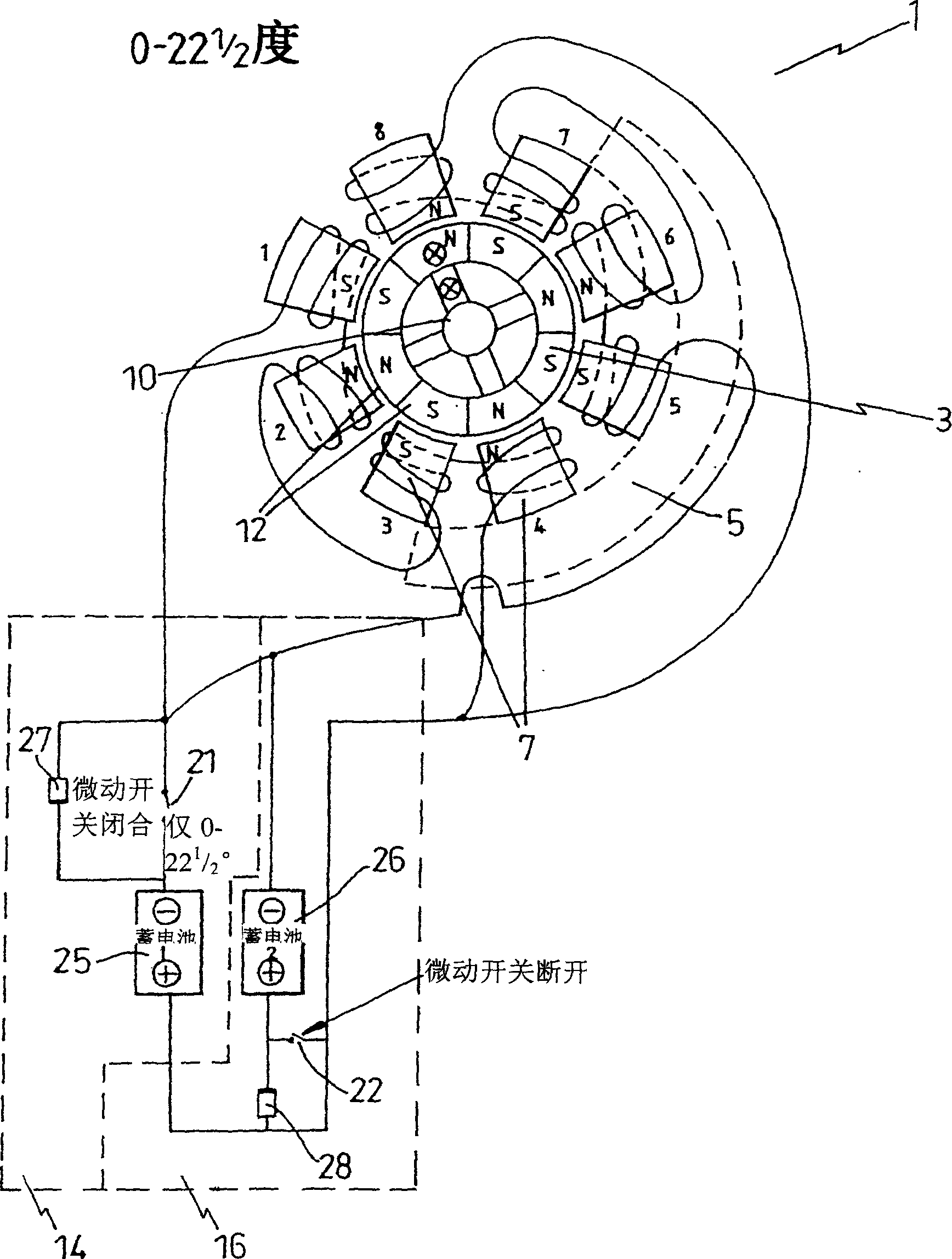
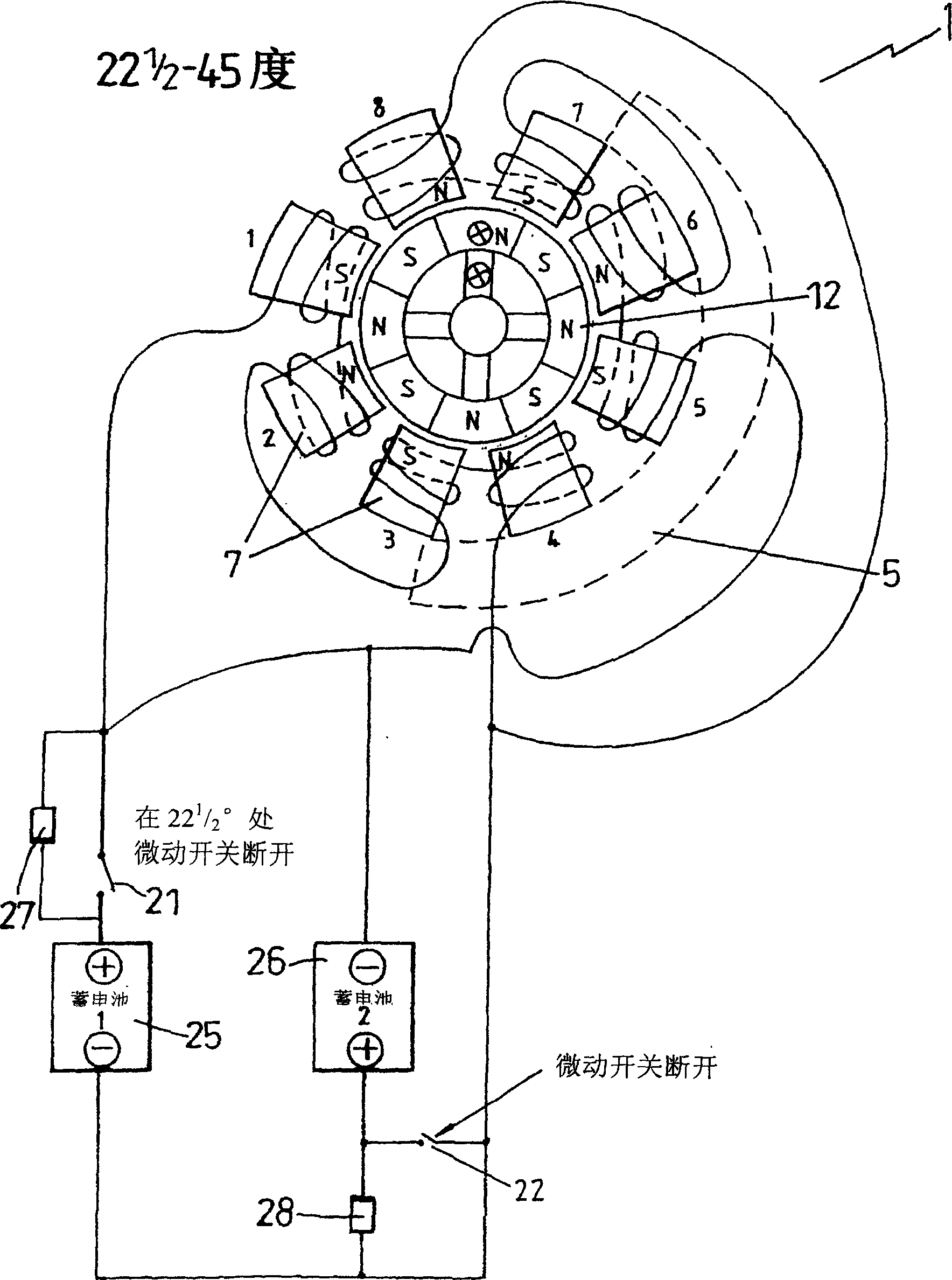
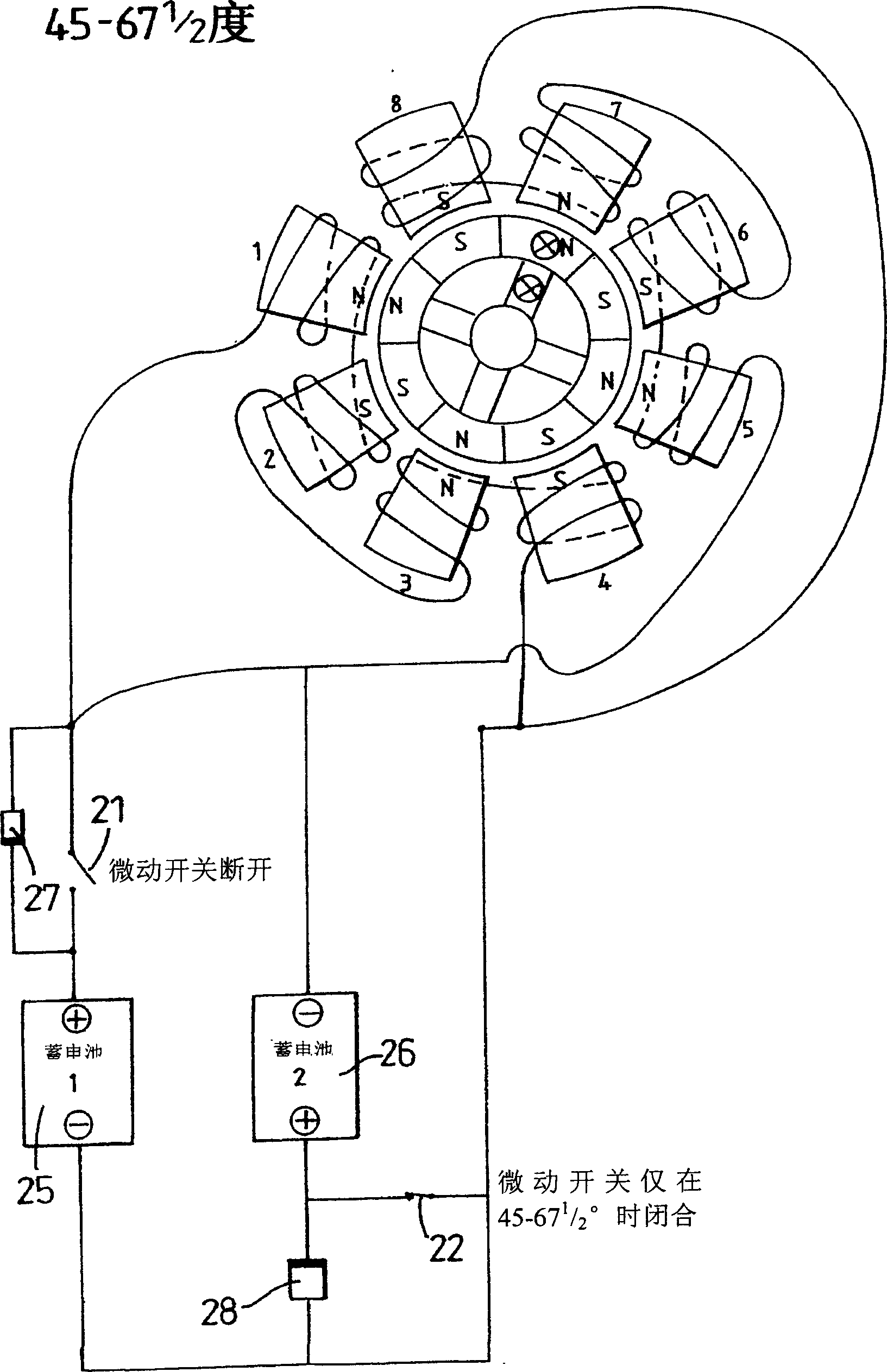
[0025] Refer to the attached drawings and first to Figures 1 to 4 , the motor has a stator 1 and a rotor 3 . The stator 1 includes an annular armature 5 (in figure 1 and 2 is represented by a dotted line, while in Figure 5 As more clearly illustrated in ), the armature 5 has a plurality of magnetic poles 7 spaced evenly along the inner circumferential surface of the armature 5 and directed towards a central longitudinal axis defined by the rotor shaft 10 . The rotor 3 is mounted for rotation about an axis 10 and has (as will be more clearly illustrated through this example) 8 permanent magnets 12 mounted on or embedded in them. Magnets arranged in series with alternating polarity extend around the circumference of the rotor 3 .

[0026] A pair of starter / accumulator circuits 14, 16 are connected in common and in series with respective sets of coils wound around the poles 7 of the stator 5, depending on the rotational position of the rotor 3 relative to the stator 5, the ...


PUM


Abstract

An electric motor has a stator and a roto. The stator (1) comprises an annular armature (5) having a plurality of poles (7) evenly spaced about the inner circumferential surface of the armature (5) and directed towards a central longitudinal axis defined by the rotor shaft. A pair of firing/accumulator circuits (14,16) are connected in common and in series with respective sets of coils wound about the stator poles. The circuits are switched into and out of contact with their respective coil sets according to the position of the rotor with respect to the stator via position sensing elements which operate switches in the accumulator circuits. In an alternative embodiment firing and accumulation is effected using commutators and electrolytic capacitors (ECP, ECN). The motor is adapted to retrieve breakdown energy of the magnetic fields to realise a more efficient motor.

Description

technical field [0001] The present invention relates to electric motors, and more particularly to an electric motor suitable for utilizing magnetic field breakdown energy. Background technique [0002] Those skilled in the art know that the relatively low efficiency of motors is due to various losses such as friction and heat losses. Of particular concern are the losses incurred during magnetic field generation, which is actually the conversion of mechanical energy into electrical energy (and vice versa). When field breakdown occurs, the energy stored in this field during motor operation is virtually completely lost. [0003] It is well known that when a voltage is applied to a coil and a magnetic field is established, if the current energizing the magnetic field is interrupted, the magnetic field breaks down releasing electrical energy that could be held. [0004] It is an object of the present invention to seek to alleviate the disadvantages of the prior art and to provi...

Claims


Application Information

Patent Timeline
IPC IPC(8): H02K21/14H02K25/00H02K29/00
CPCH02K21/14
Inventor 威廉·M·克鲁克斯
Owner 威廉 M 克鲁克斯
Why Eureka
Try Eureka