
Line capacitor

A technology of capacitors and transmission lines, applied in the field of coupling capacitors, can solve problems such as not appearing

Inactive Publication Date: 2004-08-11
AVX CORP
View PDF18 Cites 7 Cited by
  • Summary
  • Abstract
  • Description
  • Claims
  • Application Information

AI Technical Summary

Problems solved by technology

[0012] Although various solutions and alternative components have been disclosed in the field of chip capacitors and their dielectric parts, no one design solution has emerged which generally solves all the problems discussed here

Method used


Image

  • Line capacitor
  • Line capacitor
  • Line capacitor

Examples


Embodiment Construction

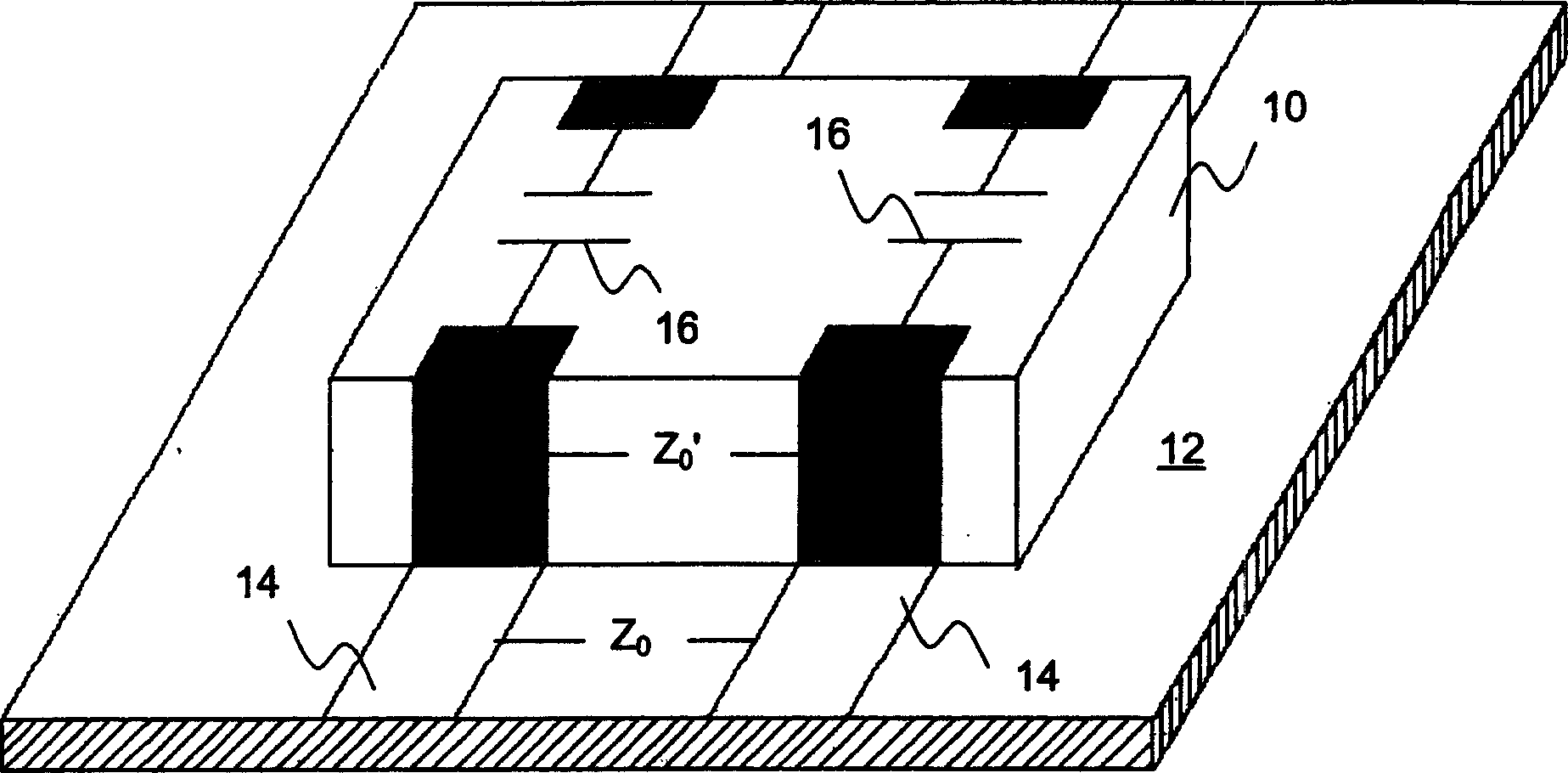
[0039] As mentioned in the Summary of the Invention, the present subject matter relates to an improved coupling device for component bonding and signal connection in a printed circuit board (PCB) environment. Such devices preferably provide the capacitive function for each parallel signal transmission path, while also maintaining important impedance values ​​between the transmission paths, referenced below Figure 1A with 1B Diagram and discuss.

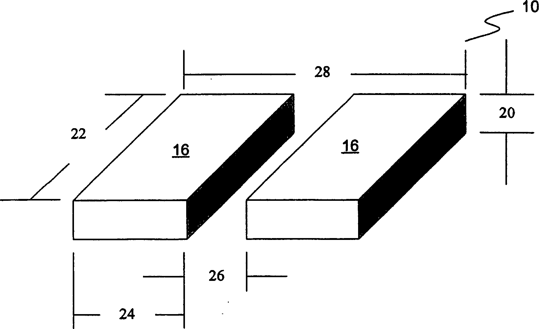
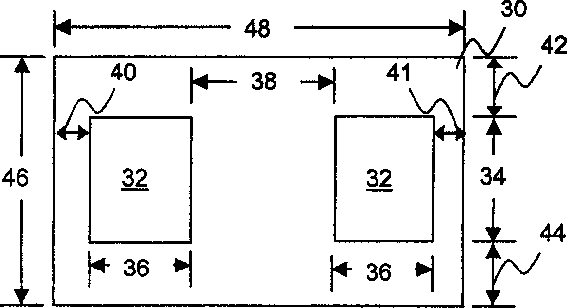
[0040] Several specific exemplary transmission line capacitor embodiments proposed herein for maintaining desired performance characteristics are described below. The first exemplary embodiment may be formed with a dielectric material having a lower dielectric constant, so that the "height" of the capacitor is high, with a fixed spacing between capacitive structures of different properties. The scheme of this first exemplary embodiment refers to respectively Figures 2A-3B be introduced. A second exemplary transmission line capaci...


PUM

PropertyMeasurementUnit
thicknessaaaaaaaaaa
thicknessaaaaaaaaaa

Abstract

A transmission line capacitor includes at least two side-by-side capacitor portions spaced apart between a separating portion all contained in a single monolithic body. Such transmission line capacitors provide specific capacitor functionality for parallel transmission lines in a printed circuit board environment, while also maintaining a desired impedance value between the transmission paths. The transmission line capacitors offer both biasing functionality for blocking undesired DC voltages as well as AC coupling functionality for passing AC voltage signals with preserved data integrity. A first embodiment may be formed with a dielectric material having a relatively low dielectric constant, allowing high capacitor 'height' with fixed spacing between distinct capacitive structures. Another embodiment may be formed with a relative high K dielectric and then slotted with an air gap between capacitive structures. Yet another embodiment may be formed with a relatively high K dielectric material, and with a relatively low K material provided in between capacitive structures. A still further embodiment concerns a transmission line capacitor design formed with high K and low K dielectric materials punched into a monolithic thin-film device.

Description

[0001] This application claims priority to prior assigned US Provisional Patent 60 / 434,930, entitled "transmission Line Capacitor," filed December 19, 2002, which is incorporated by reference in its entirety for all purposes. technical field [0002] The subject matter generally relates to a coupling capacitor for use in component bonding and signal connection in a printed circuit board (PCB) environment. In accordance with the present subject matter, when forming a transmission line capacitor, at least two capacitor structures are provided in a single monolithic device. Background technique [0003] A transmission line is generally defined as two or more parallel conductors used to connect a source to a load. Such terms often bring to mind power generation and distribution systems, which utilize large-scale transmission lines to transfer electrical energy between multiple sources and loads in an electrical network. However, transmission lines are not only used in large-sca...

Claims


Application Information

Patent Timeline
Patent Type & Authority Applications(China)
IPC IPC(8): H01G4/12H01G2/00H01G2/06H01G4/02H01G4/08H01G4/18H01G4/228H01G4/232H01G4/30H01G4/35H01G4/38
CPCH01G4/30H01G4/38H01G4/232
Inventor 乔治·科罗尼安德鲁·里特
Owner AVX CORP
Learn More