Electrolytic appts. and electrolytic treatment method

An electrolysis device and electrolysis treatment technology, which is applied in the direction of electrolysis components, electrolysis process, electrode shape/type, etc., can solve the problems of low electrolysis efficiency, low fluidity and agitation, and achieve the effect of improving efficiency

Active Publication Date: 2004-08-11
DOWA METALS & MINING CO LTD
View PDF0 Cites 4 Cited by
  • Summary
  • Abstract
  • Description
  • Claims
  • Application Information

AI Technical Summary

Problems solved by technology

[0005] However, this device that combines the existing hollow electrode and rod-shaped electrode has the problem of low electrolysis efficiency because it can only make the liquid to be treated monotonously flow and has low fluidity and agitation.

Method used


Image

  • Electrolytic appts. and electrolytic treatment method
  • Electrolytic appts. and electrolytic treatment method
  • Electrolytic appts. and electrolytic treatment method

Examples


Embodiment 1

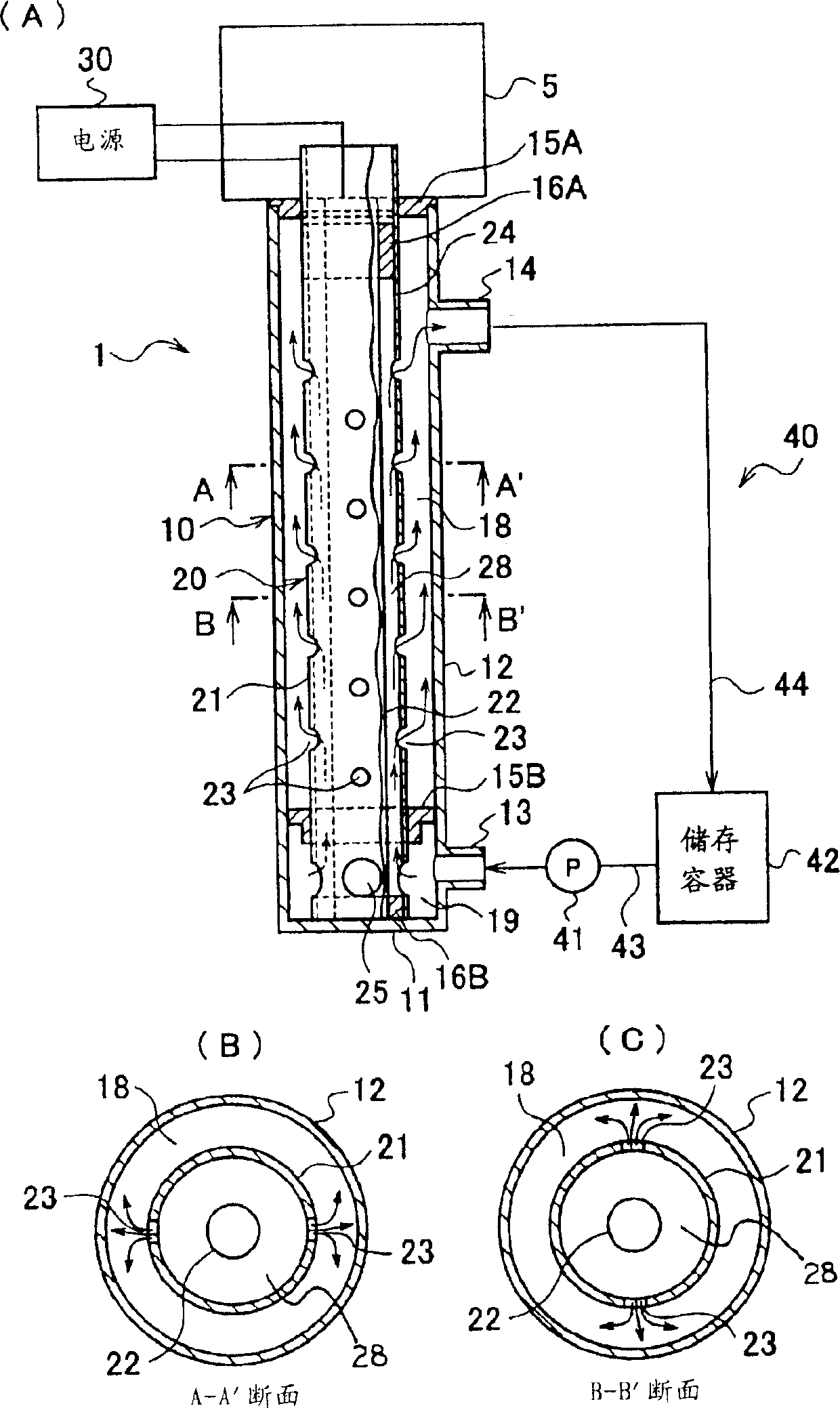
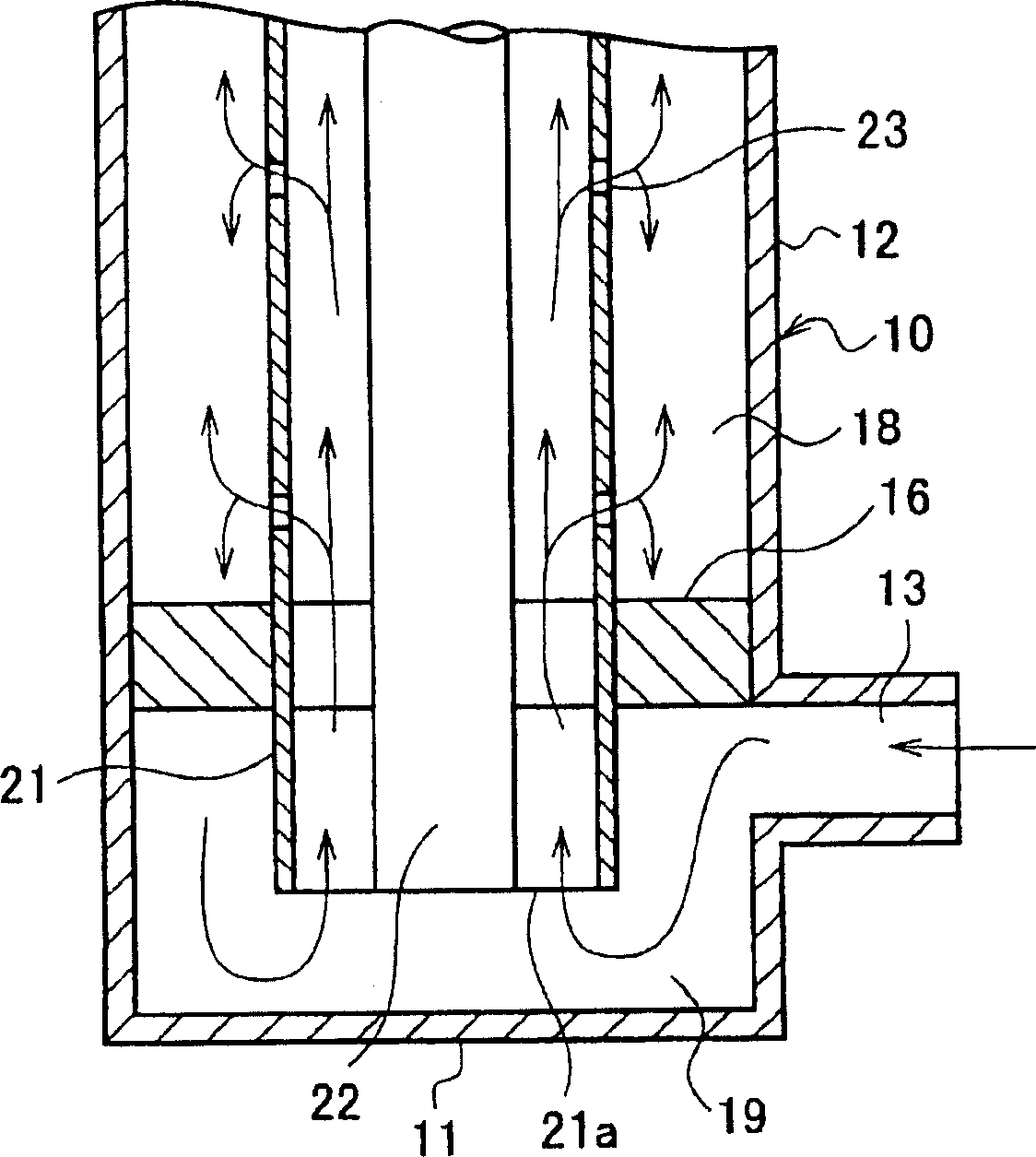
[0080] (Electrolysis Apparatus) The electrolysis apparatus shown in Fig. 1 was used. The hollow electrode as the first electrode is made of φ50×4001 stainless steel, and the rod-shaped electrode as the second electrode is made of φ30×4001 iron. On the peripheral wall of the hollow electrode, as shown in FIG. 1 , 20 through-holes of φ10 are provided at intervals in the vertical direction and at approximately equal intervals in the left-right direction.

[0081] (Solution to be treated) A gold plating solution containing 0.98 g / l of gold was used as the liquid to be treated.

[0082] (Electrolysis conditions) As shown in FIG. 4 , voltage and current were supplied to the electrodes, and the gold concentration in the liquid to be treated was measured at regular intervals.

[0083] (Electrolysis Results) The electrolytic extraction rate of gold was 2A·hr / g.

Embodiment 2

[0085] (Electrolysis device) The same electrolysis device as in Example 1 was used.

[0086] (Solution to be treated) A thin gold plating solution containing 0.91 g / l of gold was used as the liquid to be treated.

[0087] (Electrolysis conditions) As shown in FIG. 5 , voltage and current were supplied to the electrodes, and the gold concentration in the liquid to be treated was measured at regular intervals.

[0088] (Results of Electrolysis) The electrolytic extraction rate of gold was 6A·hr / g.

Embodiment 3

[0090] (Electrolysis device) The same electrolysis device as in Example 1 was used.

[0091] (Solution to be treated) A thin gold plating solution containing 0.67 g / l of gold was used as the liquid to be treated.

[0092] (Electrolysis conditions) As shown in FIG. 6, voltage and current were supplied to the electrodes, and the gold concentration in the liquid to be treated was measured at regular intervals.

[0093] (Electrolysis Results) The electrolytic extraction rate of gold was 10A·hr / g.


PUM


Abstract

To maintain compactibility, and to improve electrolytic efficiency while suppressing heat generation. A hollow electrode 21 in which many bore holes 23 are formed on the circumferential wall is arranged at the inside of a vertical, cylindrical treatment tank 10 in a state where an annular flow passage 18 is secured between the hollow electrode 21 and the inner wall of the treatment tank 10, and a rod-shaped electrode 22 is cocentrically arranged at the inside thereof. The circumferential wall 12 of the treatment tank 10 is provided with an introduction port 13 for introducing the liquid to be treated from the outside of the treatment tank 10 into the lower end of the hollow electrode 21, and an introduction-out port 14 for introducing-out the liquid to be treated flowed out from each bore hole 23 inside the treatment tank 10 at the upper end side of the hollow electrode 21 to the outside of the treatment tank 10.

Description

technical field [0001] The present invention relates to an electrolytic device and an electrolytic treatment method using the electrolytic device. Background technique [0002] Generally known electrolytic treatment device has, for example, the structure shown in FIG. In the electrolytic treatment device 50, when the electrical conductivity of the liquid to be treated is low, the size of the device has to be increased, which is uneconomical. [0003] Therefore, for example, in Patent Document 1, it is proposed to use a combination of a hollow electrode and a rod-shaped electrode arranged in the hollow electrode to form an electrode. With this technology, it is possible to compensate for the increase in the resistance value of the length direction of the electrode by expanding the end of the current introduction side. The current density is uneven, and the uneven conductivity between the intermediate electrode and the rod electrode is compensated, so that the local temperatu...

Claims


Application Information

Patent Timeline
Patent Type & Authority Applications(China)
IPC IPC(8): C25B11/02C25B9/00C25B11/03C25C1/00C25C7/00
CPCY02P10/20
Inventor 田辺文明
Owner DOWA METALS & MINING CO LTD
Why Eureka
Try Eureka