Eureka AIR delivers breakthrough ideas for toughest innovation challenges, trusted by R&D personnel around the world.

Cloth feeding mechanism of sewing machine

A technology of cloth feeding mechanism and sewing machine, which is applied in the direction of cloth feeding mechanism, sewing machine components, sewing equipment, etc., and can solve the problems that the amount of cloth feeding does not reach the expected value, difficulty in adjustment, difficulty, etc.

Inactive Publication Date: 2004-08-04
JUKI CORP
View PDF0 Cites 2 Cited by
  • Summary
  • Abstract
  • Description
  • Claims
  • Application Information

AI Technical Summary

Problems solved by technology

[0017] In addition, the up and down feed pin 124 of the up and down swing mechanism 120, since the small end surface of the pin abuts against the feed rod 102 and exerts up and down movement, and the up and down feed pin 124 is only vertically up and down relative to the swinging feed rod 102. Motion, applying up and down motion in a point contact state, so there may be problems such as bending on the feed rod or breaking due to wear and tear
[0018] And, because have the pinion 122 of swing mechanism 120 and the up and down feed cam 123 of internal gear 123a its price is expensive, hope to have other alternative mechanism
[0019] In addition, if the swing in the feed direction and the swing in the vertical direction are performed at the desired timing, since the feed amount does not reach the desired value, it is necessary to adjust their timing. However, it is necessary to change and move the vertical swing mechanism 120. The meshing teeth of the pinion gear 122 and the inner gear 123a of the vertical feeding cam 123 are complex and difficult to adjust
[0020] Moreover, when adjusting the height of the cloth feed dog 101, it is necessary to replace the upper and lower cloth feed pins 124 with different heights, which makes the adjustment difficult and complicated.

Method used


Image

  • Cloth feeding mechanism of sewing machine
  • Cloth feeding mechanism of sewing machine
  • Cloth feeding mechanism of sewing machine

Examples


Embodiment Construction

[0043] (Overall configuration of the embodiment)

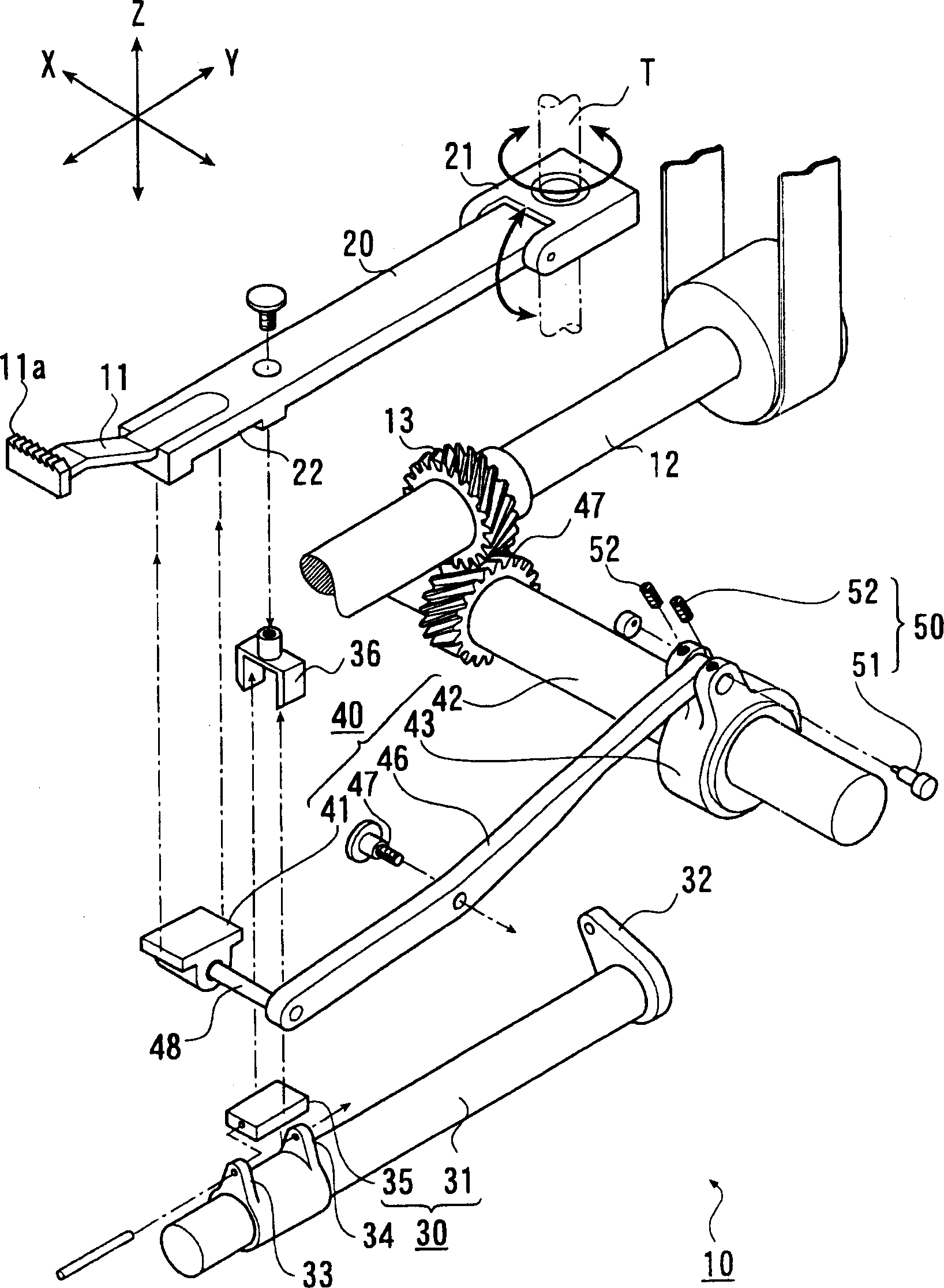
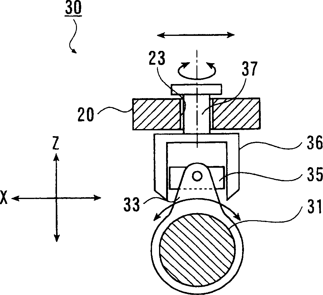
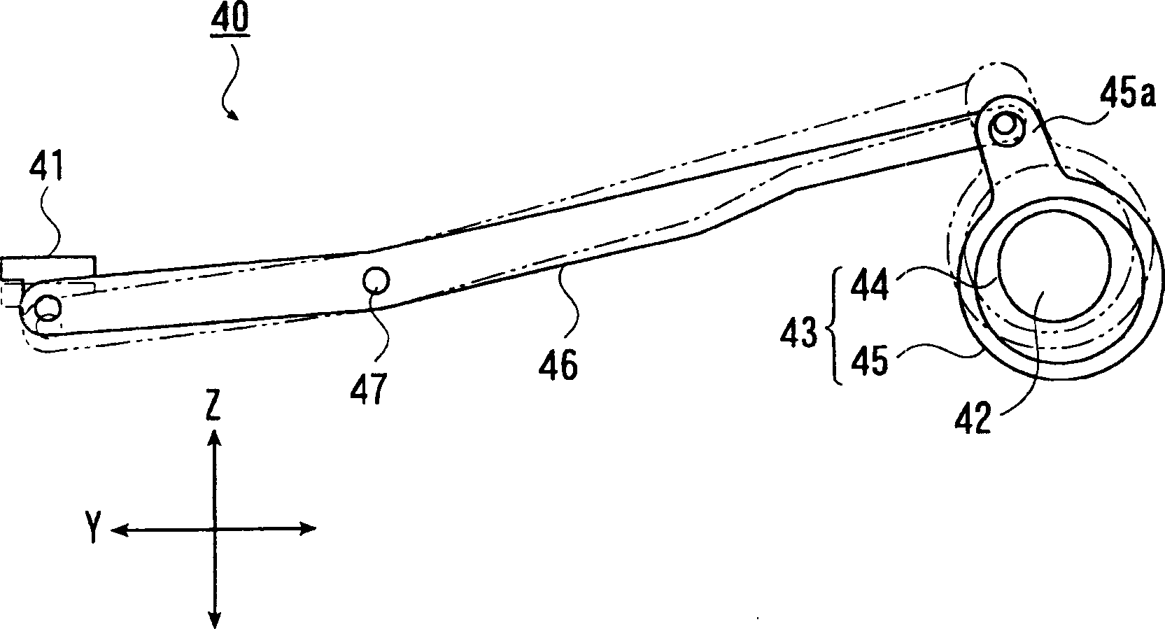
[0044] Below, refer to Figure 1 to Figure 5 Embodiments of the present invention are described. The lower feed mechanism 10 is mounted on, for example, a cylindrical sewing machine, and is a mechanism for feeding out the cloth on the throat plate in a predetermined direction by a predetermined feed amount.

[0045] The cloth feed mechanism 10 of the sewing machine has serrated teeth 11a on its upper end surface, and includes a feed dog 11 that abuts the cloth from below a needle plate (not shown) and feeds it in a predetermined cloth feeding direction 2. The front end supports the feeding dog 11 and supports the end of the feeding rod 20 so as to swing in the up-down direction and the feeding direction. The feeding swing mechanism 30 makes the feeding rod 20 swing in the feeding direction. A vertical swing mechanism 40 for swinging the cloth rod 20 in the vertical direction, and a height adjustment mechanism 50 for adjustin...


PUM


Abstract

A lower feed mechanism 10 of a sewing machine comprises a feed arm 20 with a head for supporting the feed dog 11 being so supported as to swing in a vertical direction and in a feeding direction, a feeding and rocking means 30 for rocking the feed arm along the feeding direction, and a vertical rocking means 40 for vertically rocking the feed arm 20. In the lower feed mechanism, an elliptic motion is applied to the feed dog by the feeding and rocking means and the vertical rocking means. The vertical rocking means is equipped with an arm member 46 which transmits force by the principle of leverage. The driving force for vertical swing is applied to the feed dog via the arm member.

Description

technical field [0001] The invention relates to a cloth feeding mechanism of a sewing machine with a cylindrical bottom plate. Background technique [0002] Figures 6 to 9 The cloth feed mechanism 100 of the conventional sewing machine shown has a feed dog 101 which has a serrated tooth portion 101a on its upper end surface, abuts the cloth from below the needle plate, and feeds the cloth in a predetermined conveying direction. The front end of the feed dog 101 supports the feed dog 101 and supports the feed rod 102 at the end so as to swing in the up-down direction and in the feeding direction. A vertical swing mechanism 120 in which the lever 102 swings up and down, and a needle plate holder 103 on which the needle plate 107 is placed (for example, refer to Patent Document 1). [0003] The cloth feed bar 102, such as Image 6 As shown, the base end is supported by a shaft member 104 provided on a frame of the sewing machine body (not shown), and can swing flexibly aroun...

Claims


Application Information

Patent Timeline
Patent Type & Authority Applications(China)
IPC IPC(8): D05B27/02
Inventor 渡部贵志门胁真次郎
Owner JUKI CORP
Why Eureka
Eureka Blog
Learn More