Method of improving calling route selection in special network node interface network

A node and routing technology, applied in the field of data communication networks, can solve problems such as link congestion and return when busy

Active Publication Date: 2004-07-21
ALCATEL CANADA
View PDF0 Cites 3 Cited by
  • Summary
  • Abstract
  • Description
  • Claims
  • Application Information

AI Technical Summary

Problems solved by technology

According to the PNNI busy return process of the prior art, because the ingress border node C1 is the last LGN in the call DTL stack, so the ingress border node C1 (physical node C11) generates link congestion and returns in case of busyness (C, O)

Method used


Image

  • Method of improving calling route selection in special network node interface network
  • Method of improving calling route selection in special network node interface network
  • Method of improving calling route selection in special network node interface network

Examples


Embodiment Construction

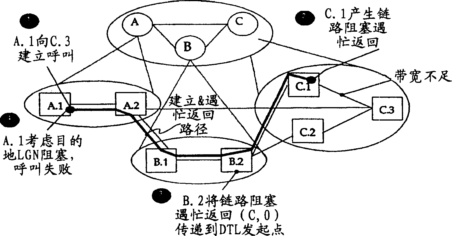
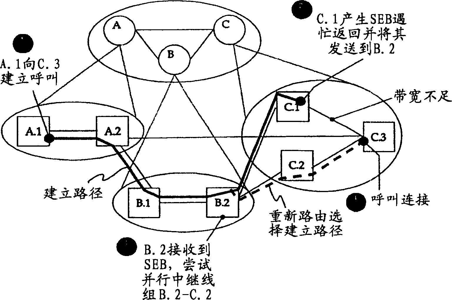
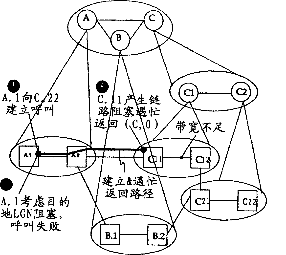
[0025] The busy return process of the present invention modifies the busy return process formulated in the PNNI specification. These procedures, referred to herein as the Destination LGN Blocking Busy Return procedure, are implemented by the ingress border node in the lowest-level destination peer group, the ingress border node in the last LGN in the DTL stack of the call (i.e. The ingress border node in the last LGN) and the DTL initiating node or the ingress border node with routing capability are used to make routing decisions based on the received busy return information.

[0026] The modified destination LGN blocking busy return process operates according to the following protocol.

[0027] Whenever an ingress border node in the lowest-level destination peer-group fails to route a call in the peer-group for any reason other than self-blocking of the physical destination node to the destination address, the lowest-level destination peer-group The ingress border node in wi...


PUM


Abstract

A method and system for improving call routing in a PNNI network using crankback messaging. A destination logical group node (LGN) blocked crankback procedure is used by entry border nodes, in the event of a failed connection attempt, to instruct preceding routing capable nodes to route the connection over another link. If the entry border node is in the lowest level peer group a Succeeding End Blocked (SEB) crankback message is sent to the preceding routing capable node. If the entry border node is not in the lowest level peer group, a destination LGN blocked crankback message is sent to the preceding routing-capable node wherein the message has special information to signal the routing node that the link into the destination LGN is blocked.

Description

technical field [0001] The invention relates to the field of data communication networks, and more specifically relates to a method for routing a call connection in a data communication network. Background technique [0002] Switching systems (also referred to as "switching networks") route data within and between data communications networks. Switching systems typically include a large number of switches or groups of switches (nodes) that provide data communication paths between various components of a data communication network. [0003] The "topology" of a switching network refers to the specific arrangement and interconnection (physical and logical) of the nodes of the switching network. Knowledge of the topology of the switching network is used to calculate communication paths in the network. [0004] For a switching system containing a small number of individual switches, its topology is very straightforward, and can be expressed by identifying each individual node i...

Claims


Application Information

Patent Timeline
Patent Type & Authority Applications(China)
IPC IPC(8): H04L12/56
CPCH04L45/04H04L45/26H04L45/28H04L45/22H04L45/247
Inventor C·拉伊斯克M·E·沙克尔
Owner ALCATEL CANADA
Why Eureka
Try Eureka