
Oil-water separatior for separating micro-seston of bilge

An oil-water separation device and tiny technology, which is applied in water treatment devices, transportation and packaging, ship parts, etc., can solve the problem that the concentration of water and oil cannot reach the discharge standard, the clogging of coalescers or adsorption materials, and the deterioration of gravity separation performance, etc. problems, achieve the effect of maintaining stable degreasing performance, preventing adverse effects, and reducing load

Inactive Publication Date: 2004-07-21
TAIKO KIKAI IND CO LTD JP
View PDF0 Cites 7 Cited by
  • Summary
  • Abstract
  • Description
  • Claims
  • Application Information

AI Technical Summary

Problems solved by technology

In ships navigating in muddy waters, since the channel contains tiny mud and sand, of course, the bilge in the locomotive room also contains a large amount of solid substances such as such tiny sand and mud. When the bilge is treated with a traditional oil-water separation device, These tiny solid substances will cause poor gravity separation performance, clogging of coalescers or adsorption materials, etc., and the oil-water separation device cannot fully function, and the oil concentration of the treated water is difficult to reach below the discharge standard.

Method used


Image

  • Oil-water separatior for separating micro-seston of bilge
  • Oil-water separatior for separating micro-seston of bilge
  • Oil-water separatior for separating micro-seston of bilge

Examples


Embodiment 1

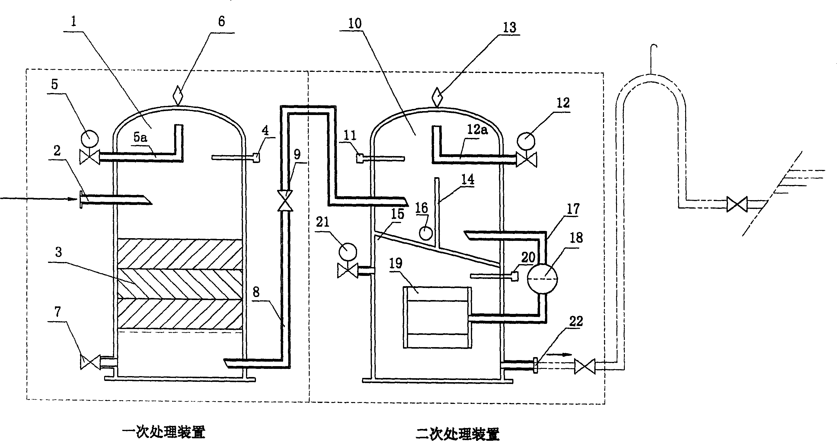
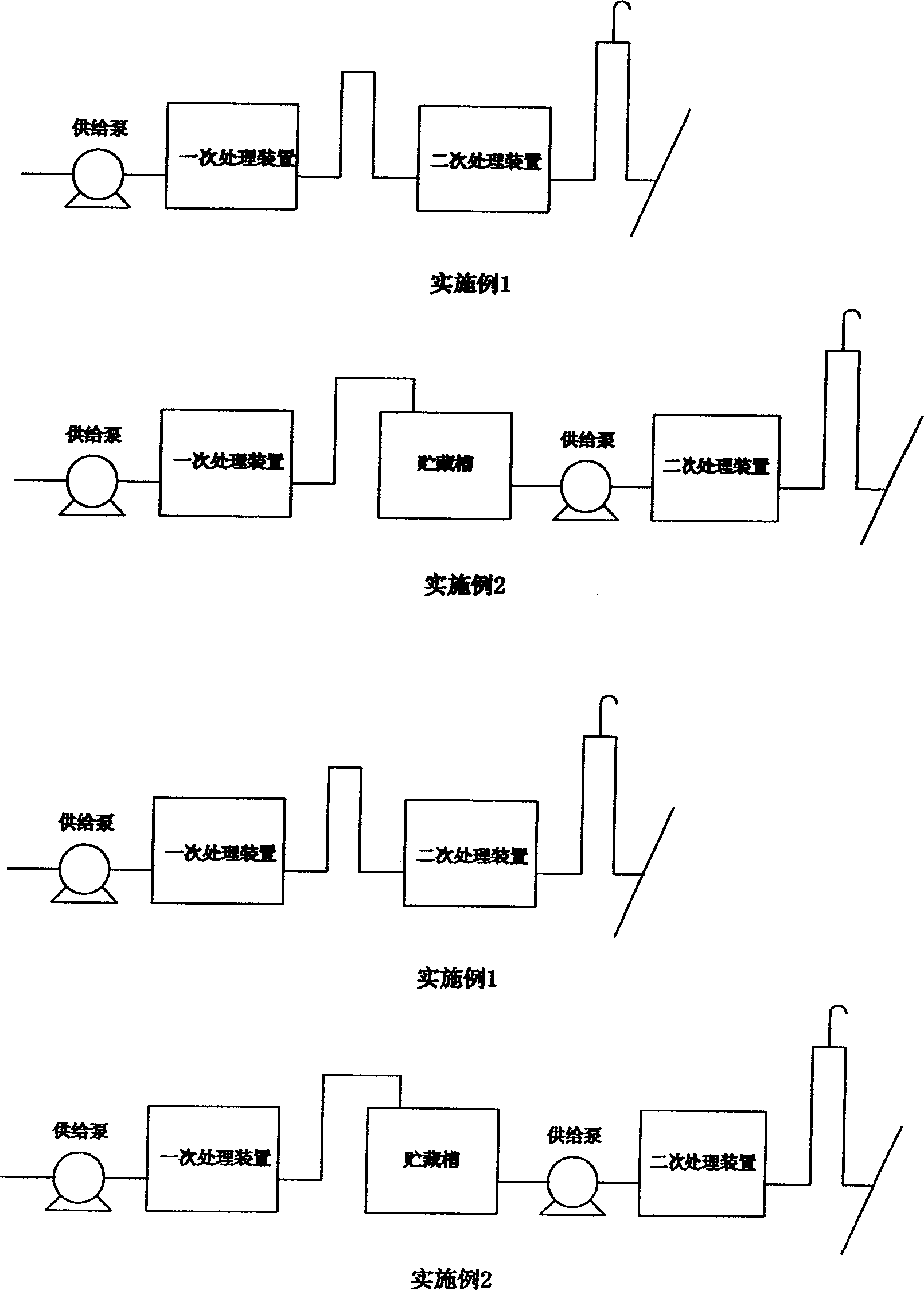
[0027] The preferred pipeline connection structure shown in Example 1, as shown in the above examples, flows from the sand filter device of the primary treatment device to the type-approved oil-water separation device of the secondary treatment device.

Embodiment 2

[0028] The pipeline connection structure shown in Example 2 is a licensed oil-water separator that allows the treated water of the sand filter device of the primary treatment device to be temporarily stored in the storage tank, and then flows into the secondary treatment device from the storage tank. Adopting this structure requires two supply pumps, so the operation and the like are more complicated than in Embodiment 1.

Embodiment 3

[0029] The pipeline connection structure shown in Embodiment 3 is a sand filter device flowing from the type-approved oil-water separation device of the secondary processing device to the primary processing device. According to this structure, the filter and the coalescer installed in the secondary treatment device will accumulate microscopic objects, requiring frequent maintenance.


PUM


Abstract

An oil-water separator for the cabin bottom to separate micro floating substance is composed of the primary treating unit for gravitationally separating oil out and removing the micro floating substance (mud and sand particles) by sand filter, and the secondary treating unit for gravitationally separating out the residual oil, collecting them by collector, and discharging the treated water.

Description

technical field [0001] The invention relates to an oil-water separation device, in particular to an oil-water separation device for separating tiny floating substances in the bilge. Background technique [0002] Traditional oil-water separation devices for ships mainly include gravity separation, coalescer and adsorption separation devices. In ships navigating in muddy waters, since the channel contains tiny mud and sand, of course, the bilge in the locomotive room also contains a large amount of solid substances such as such tiny sand and mud. When the bilge is treated with a traditional oil-water separation device, These tiny solid substances will cause poor gravity separation performance, clogging of coalescers or adsorption materials, etc., and the oil-water separation device cannot fully function, and the oil concentration of the treated water is difficult to reach below the discharge standard. Contents of the invention [0003] The object of the present invention is...

Claims


Application Information

Patent Timeline
Patent Type & Authority Applications(China)
IPC IPC(8): B63J4/00
Inventor 宫泽和规竹内健太郎
Owner TAIKO KIKAI IND CO LTD JP
Learn More